Economic Benefits of Regenerative Electronic Loads
Power supply burn-in facility lowers total energy costs by over 90% while improving space utilization; total operational savings resulted in ROI under 2 years.
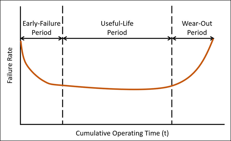
Figure 1. The classic “bathtub curve” is often used to describe the failure rates of electronic devices
Switch-mode power supplies used in data centers, industrial equipment, medical devices and other critical applications are typically subjected to burn-in operation at full load over an extended period to root out early failures and ensure reliable operation over the supply’s rated lifetime. (Figure 1.)
The traditional method of conducting these tests utilizes relatively inexpensive resistive load banks which dissipate the power output. The heat generated in the load banks is dissipated using either fan cooling or, in some cases, water cooling. Consequently, the actual energy costs of conducting the burn-in far exceed the actual power output of the power supplies under test.
The introduction of regenerative electronic loads has dramatically altered the economics of power supply burn-in testing. This article describes how the use of advanced technology, regenerative electronic loads resulted in energy cost reductions exceeding 90%. In addition to the lower energy costs, the use of regenerative loads has also resulted in improved factory floor space utilization, reduction in electrical distribution infrastructure and reduced ambient noise.
Resistive Load Banks – Simple but Often Costly to Operate
Load banks, essentially an array of power resistors, offer an inexpensive hardware solution for product burn-in. In some situations, where a small number of units are being tested and/or where a separate room is used for the tests, the load bank can be a clear, economic choice.
However, as the volume of product under test increases, resistive banks have a number of characteristics that can negatively impact efficiency, ease of use, the quality of the work environment and expense. The most obvious issue is energy consumption. For example, typical 110 kW load bank, for instance, will consume well over 110 kW of power in order to provide that function.
Click image to enlarge
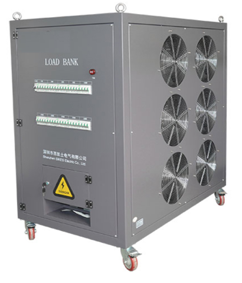
Figure 2. Fan-cooled resistive load bank adds audible noise and heat to test floor environment
High power consumption leads to cooling concerns since the heat from the load must be dealt with. Small load banks might simply require the need for added air conditioning. Most loads are fan cooled, which further increases energy consumption which can also add significantly to the ambient noise level. And for load banks that require water cooling, energy costs and significant installation expenses can be incurred. The 110 kW unit shown in Figure 1 is nearly three feet tall, takes up over eight square feet of floor space and produces 65-80 dB of audible noise.
In order to mitigate these unfavorable effects on the work environment, some manufacturers install the equipment outside the facility. This, of course, has its own concerns, including weather-proofing and potential for problems with birds and vermin.
Electronic Loads
Electronic loads, in contrast to passive load banks, typically employ active circuitry to dynamically simulate changing load profiles. Test profiles can be stored in the unit or uploaded via computer interface so that the test data can be compiled for reporting or archiving purposes. As such, electronic loads, while they can be used to simply perform a static long-term burn-in, can also subject the devices under test to step changes in the power demand and other variations in the characteristics of the load, thus providing a more reliable result of the tests. Standard electronic loads, however, still suffer from the problem of what to do with the heat generated.
Regenerative Electronic Loads
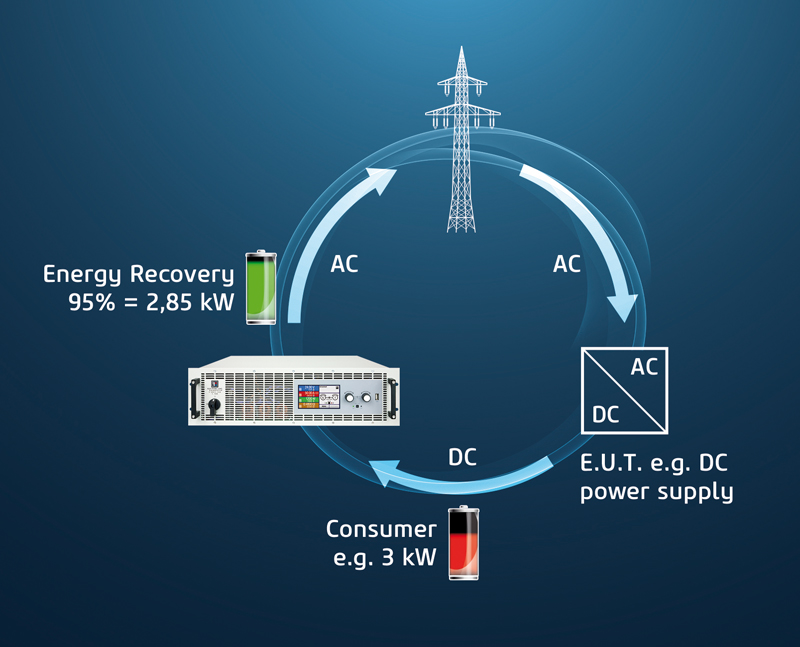
Regenerative electronic loads (ELRs) dramatically reduce the wasted energy and other problems that load banks or standard electronic loads create by redirecting the load power back to the utility using an inverter stage, synchronized to the power line input. Figure 3 illustrates how such a closed-loop system operates. Power is applied from the main to the device under test. An electronic load with regenerative output utilizes an internal micro-inverter to return the power to the mains.
Click image to enlarge
Figure 3. Closed-loop regenerative load test system returns over 90% of load energy back to grid
The results of the ELR approach are quite remarkable – with total energy consumption being reduced by up to 93%. It also has a significant effect of unit’s size, cooling requirements and audible noise. Comparing a 120 kW ELR (comprised of 4-30kW rack units) with the 110 kW load bank, the ELR dissipates just 6 kW of heat!
Other benefits of dissipating less heat means smaller cooling fans, which dramatically reduces the audible noise. Regenerative loads are also 2-3 times higher power density compared to typical air-cooled loads, which results in less rack or bench space.
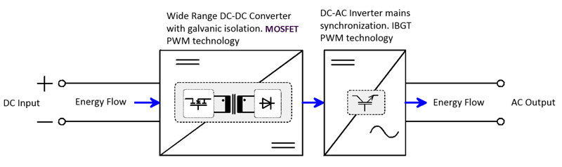
The secret to the implementation of a regenerative load bank is a back-end conversion system. As shown in Figure 4, DC energy flows into a DC-DC converter, which is tied into a DC-AC inverter (current source), and which then synchronizes with the distribution grid to recycle the energy. This technology is similar to grid-tied photovoltaic inverters (PVs).
Click image to enlarge
Figure 4. Electronic load DC output is applied to a grid-tied inverter stage
Case Study Results
A major DC power supply manufacturer was utilizing resistive load banks to conduct burn-in testing of the company’s Industrial Critical DC Power Supplies.
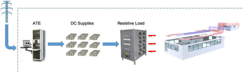
· Each burn-in station consists of nine DC supplies, each operated with a 1.38 kW DC load.
· Each burn-in station consumed 12.5 kWH (42,500 BTU) per hour over an 80-hour continuous burn-in cycle (Figure 5).
· The company’s burn-in floor hosts 24 stations amounting to 300 kW per hour of energy usage and over 1 million BTU’s of heat – per hour!
Click image to enlarge
Figure 5. Each burn-in station in the facility energizes nine power supplies at full load for 80 hours
The resistive loads in the facility were replaced by an array of 24, 15 kW ELRs, each housed in a 3U rack-mount chassis.
· The installation of ELRs has yielded a reduction in direct energy costs for each burn-in station of $7,500 per year!
· Total annual direct energy savings total $180,000.
The initial cost of the regenerative electronic loads for each test station was roughly 2.5 times the cost of the resistive loads they replaced. But because of the dramatic reduction in direct energy costs, and after accounting for the additional cost reduction benefits, as described below, the ROI was just 1.9 years!
Additional Cost Benefits
Beyond the direct energy cost savings achieved in the operation of each burn-in station, the use of the regenerative electronic loads provided these cost savings:
• Reduced operational cost and maintenance of the facility HVAC system
• Energy consumption reduction estimated at $18,000 per year.
• Maintenance costs reduction estimated at $5,600 per year.
• A regenerative load solution fits into the existing ATE racks, freeing up over 17 ft2 per station for a total of 416 ft2 once occupied by resistive load banks
• Test setup is simplified since all test equipment was within the ATE rack, saving approximately $600/station.
• Potentially reduced infrastructure cost associated with production line HVAC expansion.
• 30-40% less audible noise.
• Better working environment leads to happier operators.
Conclusion
Electronic regenerative loads provide a substantial reduction in electrical and infrastructure costs, when compared with resistive load banks. In this case study, the combination of direct energy costs plus savings due to HVAC load reduction, better utilization of factory floor space and a healthier work environment make ELRs a sound investment. Moreover, ELRs offer exceptionally versatile load profile programming and ease of set-up, making them an exceptional value on a range of dynamic testing applications.
Elektro-Automatik, USA