Sophisticated front-end management is key
To realize the potential of solar energy as a power source, the front-end interface between the cells and the energy-extraction circuitry must take into account the unique characteristics of these cells; this can be done via different algorithms and a variety of hardware/software implementations.
A representative solar installation with wireless link requires numerous sub-functions (see Figure 1), although harvesting applications will omit many of the user-oriented blocks such as a display, of course. From a high-level perspective, the power subsystem looks to be only a small part of the design, but in practice it is not: it includes a front end which interfaces to the solar cell and captures the energy from the cell; a power-management function which directs this energy to the storage element (battery or SuperCapacitor), and a power-load management block which controls the power being extracted from the storage element. The system captures energy (joules) as it is available, but releases it as power (watts) to meet the demands of the load. [Power is the rate of energy use, needed to operate the load; but this power was previously captured as energy (the time integral of power).]

Click image to enlarge
Figure 1: A complete solar-powered system, in this case for IoT, is comprised of many functional blocks; for backup or standby power, blocks such as the sensor and the RF link are not needed
As a reality, it's important to understand roughly how much power is available for extraction from solar source. The mean solar radiation reaching the upper level of the Earth's atmosphere is around 1 kW/m2, or 0.1 W/cm2.
Only a fraction of this radiation reaches the ground even on a clear day, due to atmospheric absorption, and solar cells are only about 15-20% efficient, so a good estimate is that available energy coming out of the cell to be harvested is about 10 mW/cm2. Then factor in the losses in capture, storage, and output conversion, and you can see that the amount of energy that can be obtained per square centimeter of solar cell is fairly low—and that doesn’t include the unavoidable factors of darkness, cloudiness, reduced seasonal radiation, and longitude of the siting on the Earth's surface.
Looking at this low available power makes it clear that minimizing losses throughout the solar-power system is critical, especially in mW-range harvesting applications (but at least you don’t have to worry about I2R losses there!) This optimization is most challenging at the front end, where the feeble power output of the solar cell must be extracted and captured, as any losses or inefficiencies there can't be "made good" later; that impinging solar energy is lost forever.
Efficiency begins with power-point tracking
Unlike most conventional energy (power) sources which are relatively well-behaved as current or voltage sources with fixed parameters such as internal resistance, solar cells have unusual characteristics which must be understood in order to capture as much of their output as possible. The designer's objective is to obtain maximum power from the solar cell, regardless of its output voltage and current, both of which will change as operating conditions change.
Under a given set of operating conditions, there is a unique "operating point" called the maximum power point (MPP), where the cell provides maximum power (V × I) output. To extract the power, the load the cell sees –which is the resistance of the connected circuit –must be matched to the characteristic resistance of the cell.
This matching situation is similar to the need to match any power source to a load to achieve maximum power transfer, such as between a power amplifier's output impedance and the load antenna, or from an antenna to the RF front end. In most such cases, the source and load impedance parameters are relatively constant, so the matching can be done as a fixed circuit (some applications, especially in high-performance RF, do take into account that some parameters do vary with temperature changes due to self-heating and ambient conditions).
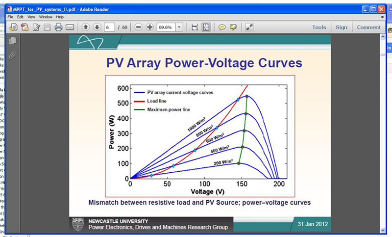
However, the operating conditions of the solar cell are never constant, and shift repeatedly due to changes in illumination, cell temperature, cell age, and other factors. As a result, the solar-based system must dynamically change its loading on the cell for maximum efficiency, called maximum power point tracking (MPPT). Effective MPPT implementation begins with the conventional graphs of source current-voltage and power-voltage relationships, with resistive load line and maximum-power line, Figure 2a and Figure 2b.

Clcik image to enlarge
Figure 2a: The a) current-voltage and b) power-voltage curves for a photovoltaic array are complex; placing the load line and managing the maximum power point are key to maximum efficiency (from Newcastle University, Power Electronics, Drives and Machines Research Group)
Click image to enlarge
Figure 2a: The a) current-voltage and b) power-voltage curves for a photovoltaic array are complex; placing the load line and managing the maximum power point are key to maximum efficiency (from Newcastle University, Power Electronics, Drives and Machines Research Group)
MPPT can be accomplished in several ways: In the "perturb and observe" technique, the front-end circuit's impedance is "dithered" while the output of the cell is monitored; if it increases, keep going in that direction, with sweeping though a range to see where the output is maximum. This is a standard approach for finding maximum/minimum in many optimization problems. Other techniques include manipulation of the cell's transconductance, by using a swept current or voltage drive to determine the internal parameters of the cell. Each method has tradeoffs, such as potential for excessive oscillation or "hunting" while seeking the MPP, or sub-optimum performance when trying to react to relatively rapid changes in the MPP.
Choices in Implementing MPPT
Regardless of the MPPT algorithm selected, the actual implementation can be accomplished in hardware via a dedicated IC, or in firmware (software) as part of the system microcontroller's programming. While the latter choice offers the most flexibility and the ability to fine-tune or even change the MPPT algorithm, it can become a system burden and so require a higher-speed, more power-hungry processor compared to a fixed-function IC. As with nearly all engineering decisions, there are tradeoffs in the decision as well as thresholds where major cost or power increments are crossed.
For small harvesting systems, a single MPPT implementation via a dedicated IC is usually the most cost effective and efficient; for multi-cell arrays spread over a larger area, even just a few square meters, it may be necessary to provide separate MPPT for each cell subsection, as individual cells and zones may have different characteristics. Choosing among a front-end IC with dedicated MPPT, a harvesting-subsystem IC with embedded MPPT, and a processor with firmware-based MPPT depends on the size of the solar array, the power levels, and the flexibility needed (or perhaps not wanted at all).
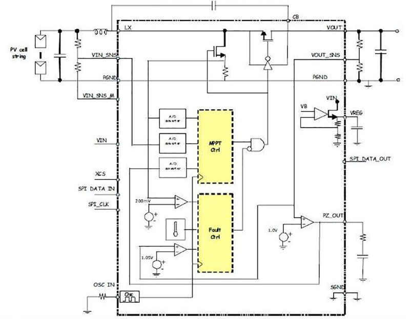
An example of a front-end IC with embedded MPPT is the SPV1020 from STMicroelectronics, Figure 3. This IC incorporates a 4-phase interleaved DC/DC boost converter to maximize the power generated by photovoltaic panels across the entire range of operating temperature and solar radiation levels. The SPV1020 operates as a PWM-controlled, fixed-frequency converter, with its duty cycle controlled by embedded logic running the perturb-and-observe algorithm. The switching frequency of the power generated converter internally with a default value of 100 kHz, but is externally adjustable from 50 kHz to 200 kHz, while the duty cycle can range from 5% to 90% with a tight step increment value of 0.2%.
Figure 3: The SPV1020 from STMicroelectronics is a DC/DC boost converter with embedded MPPT tracking algorithm, and requires no processor management in its basic operation.
Click image to enlarge
Figure 3: The SPV1020 from STMicroelectronics is a DC/DC boost converter with embedded MPPT tracking algorithm, and requires no processor management in its basic operation.
The vendor maintains that since the MPP is computed locally, system-level efficiency is higher than can be achieved using topologies where the MPP is computed at a centralized inverter. Within the IC are power MOSFETs (for active switches) along with synchronous rectifiers, thus minimizing the number of external devices. For long-term reliability, the 4-phase interleaved topology of the DC/DC converter eliminates the need to use electrolytic capacitors, which are often the limiting item when striving for long system lifetime. Designers can use multiple SPV1020s in a panel array, with one device per panel; these panels can be connected in series, in parallel, or series/parallel combinations. The vendor also offers a selection of evaluation boards for this IC, showing its use at different power levels and configurations.
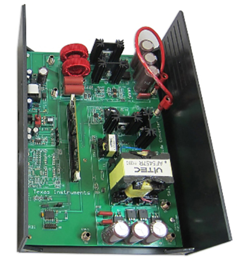
At the other end of the complexity and flexibility spectrum is a fully programmable controller, such as the TMDSHVMPPTKIT high-voltage, isolated solar MPPT developer's kit from Texas Instruments. This complete evaluation-board package, Figure 4, targets high-power systems with 200-300 VDC input and up to 500 W capability. It is based on the Piccolo F28035 processor in the C2000 family, and a two-phase interleaved boost stage for maximum power point tracking, along with a half-bridge resonant LLC isolation stage; both are digitally controlled from a single MCU. Designers can select MPPT by either incremental-conductance or perturb-and-observe algorithms, allowing them to test the two options and associated effectiveness in their application.
Figure 4: For a fully programmable solution, the TMDSHVMPPTKIT from Texas Instruments is a high-voltage, isolated solar developer's kit with available MPPT algorithms, based on the Piccolo F28035 processor; it can support supplies in the 500 W range.
Click image to enlarge
Figure 4: For a fully programmable solution, the TMDSHVMPPTKIT from Texas Instruments is a high-voltage, isolated solar developer's kit with available MPPT algorithms, based on the Piccolo F28035 processor; it can support supplies in the 500 W range.
It also includes USB-connected JTAG emulation, which eliminates the need for external hardware, and a quick start graphical user interface. All hardware and software is fully documented, and provided as "open source" for design use. The evaluation board complements the TMSHV1PHINVKIT from TI; together, they provide a complete DC-to-AC solar-powered inverter system.
An intermediate-size MPPT approach uses a device such the PIC16F1503 microcontroller from Microchip Technology. This IC is one of a series of enhanced core devices which includes peripherals such as an NCO (numerically controlled oscillator), CWG (complementary wave generator) or CLC (configurable logic cell). Microchip provides details including MPPT flow charts and associated code modules in their application notes; both can be used with the PIC device while the flow charts alone can be used as a guide for any processor programming effort.
The attraction of solar power as an apparently free and never-depleted source for circuits ranging from small IoT class to large backup and even primary power is strong, with good reason. However, the power available to be extracted is fairly small, at best, so any design must focus on efficiency at the front end, such as MPPT issues, to make such an approach both economically sensible and technically feasible. Whether designers choose dedicated front-end ICs or fully programmable, processor-based designs depends on the solar array size, physical layout, desired modularity, and cost, of course.