Electrical Safety Testing of Cables and Connectors

High-voltage, programmable multi-point switching system facilitates the process and ensure safe and error-free compliance with standards
Figure 1. Voltage is applied to one conductor at a time while adjacent conductors are bundled. Resistance is calculated based on leakage current
Electrical safety (hipot) testing is critical in ensuring compliance with a host of electrical safety standards and in confirming the assembled product is free from electrical or mechanical defects. Hipot testers are used to measure leakage current and insulation resistance between components and connections, confirm solid ground connections and test ground bonds. When testing multi-conductor cables and connectors, these tests require the sequential application of precise and controlled high voltages or currents between pairs of elements then accurately measuring and recording the results. This process is best conducted using a combination of a programmable, electrical safety tester and a programmable multi-point switching device.
Dielectric Withstand - Hipot
The basic hipot test applies a high voltage from the conductors to the chassis of the device-under-test (DUT) or between conductors in a cable or between pins in a connector/cable combination. This test is often referred to as “dielectric” or “voltage” withstand. Its purpose is to confirm that the insulation and isolation of the non-conducting surfaces from the operating voltage is sufficient to avoid a shock hazard. The typical specification for this test is: 2x (normal operating voltage) + 1000V.
A three-conductor power cord connected to an electronic device would require a voltage withstand test between the conductors as well as a ground bond test between the ground wire and the chassis. To perform this simple requirement involves twelve separate connections.
Depending on the applicable standard, passing this test requires:
· the leakage current measured is less than the maximum allowable current.
· no breakdown occurs, i.e., no sudden and uncontrolled flow of current
Cable and Connector Hipot Testing
In many instances, insulation resistance needs to be measured between several conductors. Examples include cable/connector assemblies, multiconductor cables and relays. To make this measurement, all the conductors except one are shorted together and the test voltage is applied from the remaining conductor across the bundled ones. Each wire is then, in turn, tested in this fashion (Figure 1).
Cable and connector hipot tests require making multiple measurements. A connector assembly with multiple pins would require a unique test for each pair of contacts as well as between each contact and adjacent wires and then the connector body. A simple four-conductor cable might require 20 separate tests:
1) Continuity on each wire – 4 tests
2) Insulation resistance between each wire and ground or shell – 4 more tests
3) Insulation resistance from each wire to all the other wires – 12 additional tests
For a 24-conductor cable, the total number of individual tests could be as high as 578.
Doing this manually is not only labor intensive, it is also highly susceptible to errors:
· Were all the combinations tested?
· Were some inadvertently duplicated?
· Have all the test conditions been implemented?
In many cases, a programmable, multi-point switching system is an essential tool to quickly, safely and accurately implement the entire series of electrical safety tests. Using a fixture to quickly connect the entire assembly, a multipoint switching unit serves as an interface with the hipot tester and automatically sequences the testing through all the combinations. As “simple” as this sounds, a great deal of engineering and innovation goes into these devices.
Cable and Connector Test System Components
To conduct the sheer number of tests that are often necessary in a safe and accurate way, the recommended multipoint test system would include the following:
· A programmable hipot tester
· A programmable high voltage switching system
· Software for controlling the test sequences.
[An example of such of such a system would be a Vitrek V7x Series or 95x Series Programmable electrical Safety Tester, a Vitrek 964i Programmable Multipoint Switching System and QT Enterprise software.]
Anatomy of a High Voltage Multi-point Switching System
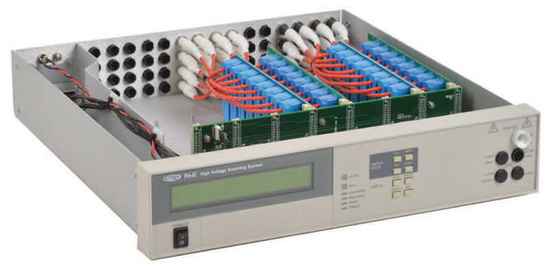
Click image to enlarge
Figure 2. Open view of the Vitrek 964i shows an array of relays capable of handling high voltages and currents
The function of an automated switching system (figure 2) is to route test signals and return signals to any desired test points. The device (working in combination with a hipot tester) should be capable of:
· Performing hipot/continuity/ground bond at various points, etc.
· Applying high voltage or current to multiple points
· Measuring circuit L/C/R at various points, etc.
· Measuring or applying other signals at various points
(500 Hz maximum frequency) etc.
Important Features of Multi-point Switching Systems
The functionality of a multi-point switching system is improved when the device offers a number of key features:
· Flexibility. The ability to combine different combinations of relay configurations. In some instances, the cable/connector/chassis under test will require a combination of tests, including insulation resistance between conductors and ground-bond testing, requiring higher voltage and current capabilities.
· Front Panel Input Connections. The ability to easily connect the switching system to its companion hipot tester.
· Self-Testing. The test is only as valid as the test setup. An essential function of a multipoint switch is its ability to confirm proper operation on a continuous basis.
· Reliable High-Speed Operation. The capability to change states rapidly is important, particularly in applications requiring hundreds of reconfigurations of the switch settings to test all possible variations. The Vitrek 964i, for example, can fully reconfigure the switch settings in as little as 5ms.
· Automatic Maintenance Alerts. Accumulating counts of relay operations for each relay is important to track if any relay is approaching (or beyond) its life expectancy.
· High Voltage and Current Capability. The relays need to be able to withstand “fault” conditions in the DUT without malfunction.
Test System Software
While advanced hipot testers and multi-point switching devices each have front panel controls capable of programming and operating test sequences, utilizing system software to configure and control both the hipot tester and the switching system affords additional benefits, including:
· Ability to reliably upload the system for a variety of test configurations
· Ability to download, record and document test results.
Conclusion
Multi-point high-voltage and current testing of power connections and cable assemblies can involve dozens and even hundreds in individual point-to-point tests. Performing these tests manually is not only a daunting task but one fraught with the potential for errors.
Devices like the Vitrek 964i Programmable High Voltage Switching System in combination with a programmable electrical safety tester provides the answer to efficient setup and execution of these tests. In addition, utilizing system software such as Vitrek’s QT Enterprise provides a comprehensive and adaptable testing solution.


