Single-Pair with Power-over-Ethernet from an EMC perspective
Figure 1: PSE (board in the picture below) and PD (board in the picture above) of the Reference Design RD041 during start-up
With just one twisted pair of wires, Single-Pair Ethernet is a convincingly lean solution. This cabling becomes even more efficient if it is also used for power supply in addition to data transmission - this is referred to as "Single-Pair with Power-over-Ethernet" (SPoE). What about electromagnetic compatibility? Würth Elektronik has investigated this using its own SPoE reference design.
There are many possible applications for a 10 Mbit/s SPoE interface with integrated energy transmission, such as the operation of sensors at long distances. With the growing demand for data and power in areas such as industrial automation, automotive and IoT networks, SPoE (often referred to as Single-Pair Ethernet with Power-over-Data-Lines - SPE PoDL) offers an efficient solution that enables both data and power transmission over a single twisted pair of wires. This article deals with the EMC behavior of the SPoE reference design RD041 from Würth Elektronik [1], focusing on the low emissions and high immunity to continuous and transient disturbances.
SPoE reference design and test setup
The reference design RD041 in Figure 1 is an Ethernet interface that transmits data over two wires and simultaneously supplies power, combining “Single Pair Ethernet” (SPE) with “Power over Data Lines” (PoDL).
SPE enables Ethernet communication with only one pair of wires, making it ideal for space-saving and cost-sensitive applications in industrial, automotive and IoT devices. PoDL extends Power over Ethernet (PoE) to SPoE enabling power and data transmission over a single twisted pair of wires, simplifying installations and reducing costs.
To carry out the EMC tests, the reference design consisting of 2 boards (Powered Device - PD and Power Sourcing Equipment - PSE) is operated with a defined transmission path as the test object.
Figure 2 shows this transmission path with the auxiliary equipment required for operation shown in gray. A shielded SPE cable or an unshielded twisted pair cable can be used as the transmission path between the PD and PSE. Laptop 1 is connected to the PD via a shielded 10 Mbit/s Ethernet interface. It receives its IP address from the DHCP server (WLAN router) via the SPoE interface, which connects the PSE and PD. The PD is powered by the PSE board.
The PSE part of the reference design has a 24 V input that supplies the SPoE reference design. In the reference design, this connection is designed as a port on the local DC power supply network. The 10 Mbit/s interface is connected to the router via a shielded Ethernet cable and then on to the Laptop 2 being evaluated. Both laptops receive their IP addresses from the DHCP server. The reference design is therefore ready and can be used as an adapter to extend an Internet connection in a plug-and-play manner.

Click image to enlarge
Figure 2: Test setup for evaluating the performance of the SPoE reference design
Test software and performance criteria
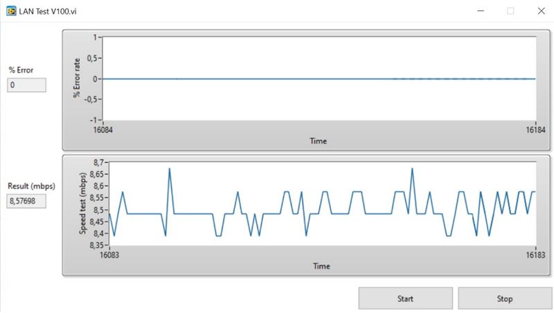
Laptop 1 serves as a server that sends known test data to Laptop 2. This evaluates the error rate in the transmission and the transmission speed using a Windows application. This monitoring application has already been successfully used in the application notes for the GB-Ethernet design (ANP116 and ANP122) [2,3].
Figure 3 shows that an average transmission rate of slightly less than 9 Mbit/s can be achieved. In the selected test case, the packets have a short transmission time compared to the tests on the Gigabit Ethernet interface. During the tests, it is therefore possible to test with a measurement and reaction time of one second.
Click image to enlarge
Figure 3: Monitoring of the SPoE interface. PSE and PD are connected to the network via an Ethernet interface
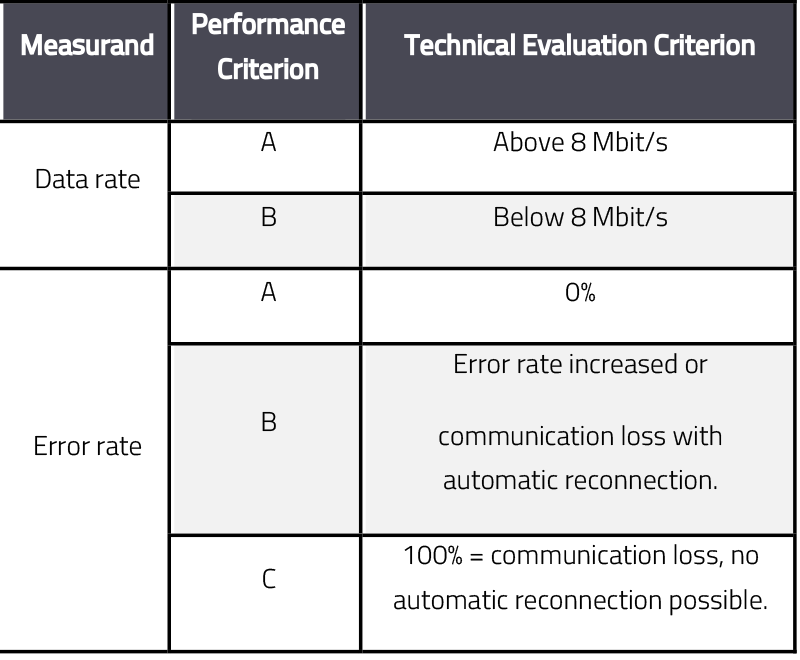
During the immunity tests, the performance of the reference design is checked against the criteria in Table 1.
Click image to enlarge
Table 1: Performance criteria of the SPoE reference design
When evaluating the performance criteria, the auxiliary equipment also has a relevant impact on the performance of the transmission path. For example, the transmission error rate increased when a WiFi interface was used between the router and Laptop 2 instead of a shielded Ethernet cable.
Shield connection of the Ethernet interface
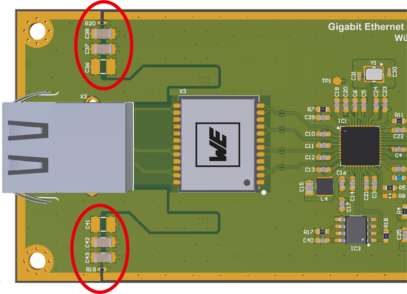
As already shown in Application Note ANP116 [2], the following components are suitable for connecting the shield of the Ethernet socket to the GND plane of the board as shown in Fig. 4:
- 2 × 10 nF X7R 1206 MLCC 100 V (part no. 885012208112)
- SMT varistor (part. no. 82551600)
The shield connection is used for the SPoE interface and for the 10 Mbit/s Ethernet interface. The varistor is not shown in Figure 4. This can be placed parallel to the capacitor on one side. The USB interface on the boards is not used for the analyses in this article.
Click image to enlarge
Figure 4: Shield connection of the Ethernet socket according to ANP116. There is an MLCC on each side, the varistor is not shown
Emission of the reference design
The emission of the reference design in the configurations described above is analyzed below. The USB interface is not used for the emission measurements in accordance with CISPR 32; communication takes place exclusively via the Ethernet and SPoE interfaces.
Radiated emissions
PD and PSE are operated and tested together to test radiated emissions. The cable length at the SPoE interface for the emission test is 1 m horizontally in the field between the two boards.
The PSE is supplied with 24 V via feed-through filters from a laboratory power supply unit located outside the anechoic chamber. The PSE and PD are located inside
the full anechoic chamber, whereby the PSE is connected via 10 Mbit/s Ethernet with a shielded cable to an Ethernet fiber optic converter, which establishes the connection to the router and Laptop 2 outside the measuring hall. The PD is connected to Laptop 1 via a shielded Ethernet cable, which is inside a shielded box (Fig. 2).
This setup prevents interference from the router or the laptops being measured during the emission tests. As this set-up is also used in the radiated immunity test, the laptops and the router are also protected from being affected by the electric field of the immunity test.
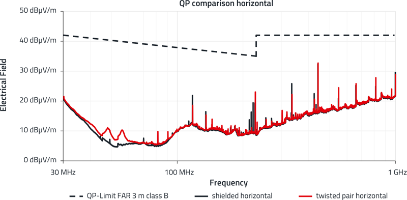
The interference spectrum of the reference design in Figure 5 is at least 9 dB below the limit value for both cable types used and the results are comparable.
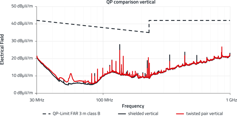
Click image to enlarge
Figure 5 (a) and (b): Comparison of the radiated interference emission of the SPoE reference design when using shielded SPE cable or unshielded twisted pair cable
Radio interference voltage
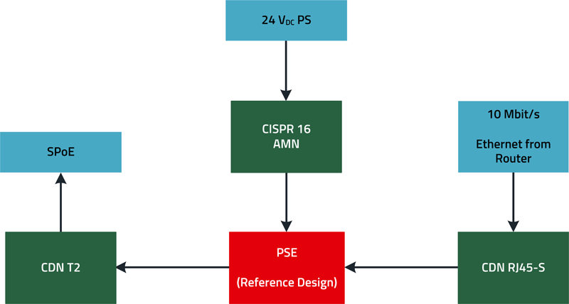
The PSE and the PD may be physically separated in the subsequent setup and are therefore tested individually. The DC input of the PSE is to be tested as a possible DC mains input, the Ethernet cable of the 10 Mbit/s Ethernet interface and SPoE interface are to be regarded as a long network cable. The emission of the DC input on the PSE is measured in accordance with CISPR 16 with a 50 µH AMN (Artificial Mains Network), the emission of the network ports is measured using 150 ΩCDNs (Coupling Decoupling Network), which act as an AAN (Asymmetric Artificial Network). The test setups for measuring the radio interference voltage at the PSE and PD are shown inFigures 6 and7.
A CDN T2 is used to test the SPoE interface with an unshielded twisted-pair cable; when measuring the interference on the shielded SPoE interface, the emission is tested using a self-built CDN for shielded SPE cables. The interference on the shielded Ethernet cable is measured using a CDN for shielded Cat5e cables. Network replicas and CDNs must always be terminated with 50 Ωin the test setup (either by the test receiver or by means of a 50 Ωresistor).
Click image to enlarge
Figure 6: Measurement setup for testing the radio interference voltage on the PSE
Click image to enlarge
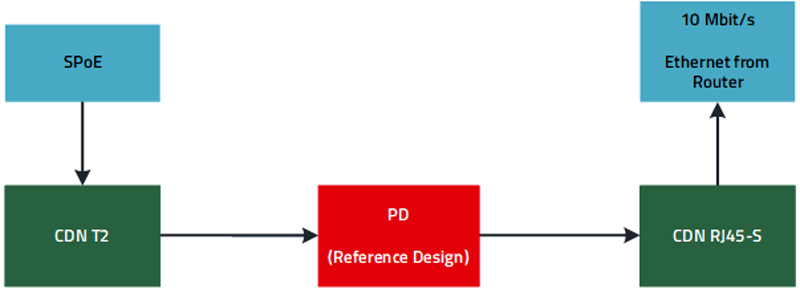
Figure 7: Measurement setup for testing the radio interference voltage on the PD
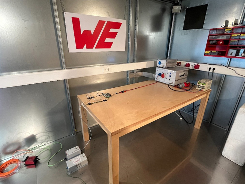
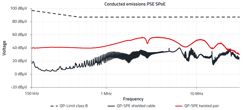
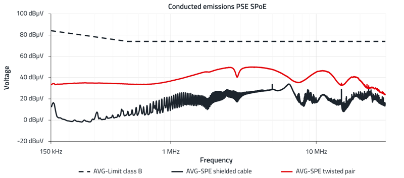
The measurement setup of the conducted interference emission on the PSE board of the SPoE reference design is shown in Figure 8. The measurement results of the conducted emissions on the SPoE interface of the PSE are shown in Figure 9, with the results of the quasi-peak detector at the top and the mean value detector at the bottom. Further measurement results of the conducted emission test are shown in detail in Application Note ANP141 [4].
Click image to enlarge
Figure 8: Measurement of the conducted interference emission on the PSE board of the SPoE reference design
Click image to enlarge
Click image to enlarge
The SPoE reference design is characterized by low radiated and conducted emissions. Despite open circuit boards without a shielded housing, the emission results are well below the EMC limit values for residential areas. Even with an unshielded twisted pair cable, the results of the SPoE interface are well below the EMC limit values for all measurements. From the point of view of emission testing, shielding of the SPoE interface is therefore not necessary.
Interference immunity of the reference design
A detailed examination of the immunity of the reference design to continuous and transient interference as well as the ESD behavior is beyond the scope of this article. Therefore, please refer to the comprehensive Application Note ANP141 [4], where you will find a detailed description of the test setups and measured values.
References
[1] Zenkner, H.: Design of a Single Pair Ethernet System with Power over Data Lines (SPoE). Reference Design from Würth Elektronik RD041: www.we-online.com/RD041
[2] Stirn, A.: Gigabit Ethernet interface from an EMC perspective. Application Note from Würth Elektronik ANP116: www.we-online.com/ANP116
[3] Stirn, A.: Gigabit PoE Interface from an EMC perspective. Application Note from Würth Elektronik ANP122: www.we-online.com/ANP122
[4] Stirn, A.: The SPoE Interface from an EMC Perspective. Application Note from Würth Elektronik ANP141: www.we-online.com/ANP141

.jpg)