Enhance AC Line Switching Efficiency and Reliability in HBA and Smart Home Applications by Using Lossless Zero-Cross Detection: Part 3 of 4

LinkSwitch-TNZ
Optimizing the performance of devices that turn AC line power on and off is an important consideration in a growing variety of applications, including home/building automation (HBA), Internet of Things (IoT)-enabled appliances, smart switches and plugs, dimmers, and occupancy sensors, and especially in designs that employ a relay or TRIAC for power control. When AC power is switched on or off asynchronously without considering the voltage at which it occurs, efficiency and reliability are adversely impacted, and circuits must be added to protect the switch from high transient currents.
When AC power is turned on asynchronously, surge currents can exceed 100 A. Repetitive exposure to high surge currents negatively impacts the reliability and lifetime of relays and TRIACs. The life expectancy of the electrical contacts is reduced by surge current demands and is often limited to 100,000 operations, although mechanical life expectancy may be one million, 10 million, or even 100 million operations. Considering TRIACs, progressive gate degradation can also occur when controlling loads that present low initial impedance. In both cases, minimizing or eliminating surge currents contributes to longer life expectancy and higher reliability.
For relays, if the device is opened (turned off) when the input voltage sine wave is at a high point in the cycle, an arc can develop across the contacts, which will erode the surface of the contact. With semiconductor line switches, switching losses can be reduced by arranging turn-off to occur at the AC zero crossing. This will also reduce device stress by eliminating arcs and remove the need for inrush-limiting circuits.
A discrete circuit can be implemented to detect the AC line zero-crossing point to control the turn-on and turn-off transitions of the main power device, thereby reducing switching losses and inrush current. This approach is more efficient but requires extra components, takes up valuable board space, and is still lossy, consuming almost half of the allowed standby power budget in some cases.
The optimal zero crossing detection solution
To address this challenge, LinkSwitch-TNZ offline switcher ICs from Power Integrations combine a 725 V power MOSFET switch, a power supply controller and a lossless zero-crossing detector (ZCD) in a single device. Use of the LinkSwitch-TNZ family results in AC/DC power supplies with high efficiency, low standby power consumption, minimum component count and AC zero-crossing detection.
The LinkSwitch-TNZ IC’s ZCD produces an output signal that is sent to the microcontroller and controls the power switching relay or TRIAC, ensuring that the device can be turned on and off at the zero crossing point every time. The ZCD signal logic follows the AC line, and the signal toggles every half cycle (Figure 1) at the zero-crossing point. LinkSwitch-TNZ devices use less than 5 mW, qualifying them as having zero power consumption. This compares very favorably with 50 to 90 mW of power consumption in typical discrete ZCD implementations.
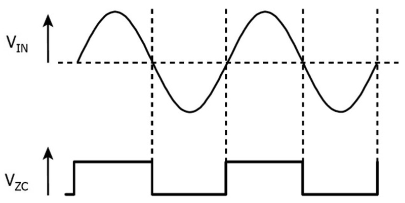
Click image to enlarge
Figure 1: The ZCD signal logic follows the AC line and the signal toggles every half cycle at zero voltage transitions
The LinkSwitch-TNZ buck or flyback mode converter switches at 66 kHz which reduces the size and cost of magnetics and output capacitors and allows the use of low-cost, off-the-shelf inductors in a buck implementation. Frequency jitter reduces electromagnetic interference, reducing filter complexity. A full suite of safety features protects the device and the system against input and output overvoltage, device over-temperature, lost regulation, and power supply output overload and short-circuit faults.
LinkSwitch-TNZ ICs can reduce standby power consumption by up to 60% and consume less than 100 μA in standby, resulting in power supply designs that can easily meet no-load and standby regulations worldwide. Component count can be reduced by more than 40% using this highly integrated device family, and designs are more flexible than discrete implementations.
The device family supports flyback, buck and buck-boost topologies, and includes devices with and without an integrated X-capacitor discharge function. When used as an auxiliary power supply in larger systems, the X-capacitor discharge feature eliminates permanently inline bleeder resistors, further reducing standby power consumption. LinkSwitch-TNZ devices are suitable for all common topologies, with or without optocoupler-based feedback.
Non-isolated buck converters
Figure 2 shows the typical output current for LinkSwitch-TNZ devices in a non-isolated buck converter with devices operating at default current limit and adequate heat sinking ranges from 63 mA to 575 mA. Operating modes are mostly discontinuous conduction mode (MDCM) and continuous conduction mode (CCM).

Click image to enlarge
Figure 2: In the LinkSwitch-TNZ part numbers, x = 0 for devices with zero-cross function only and x = 1 for devices with both zero cross and X-capacitor discharge functions
Selecting between MDCM and CCM operation
When choosing between MDCM and CCM operation, designers should pick the LinkSwitch-TNZ device, freewheeling diode and output inductor that results in the lowest overall solution cost while delivering sufficient power. In general, MDCM provides the lowest cost and highest efficiency converter. CCM designs require a larger inductor and ultrafast (tRR 35 ns maximum) freewheeling diode in all cases but provides more output power.
Isolated flyback converters
The maximum practical continuous output power in a flyback design is shown in Figure 3.
Click image to enlarge
Figure 3: Maximum practical continuous power that the LinkSwitch-TNZ can deliver under different line conditions
In flyback designs, the LinkSwitch-TNZ can deliver over 80% efficient power conversion. In addition, the use of on/off control enables very low power consumption at light loads and allows for more functions – such as display, wireless connectivity, sensors etc. – to be active during system standby.
Evaluation boards to jump-start projects
To help designers accelerate projects, Power Integrations offers a range of evaluation boards for the LinkSwitch-TNZ IC family, including 0.5 W and 2.5 W non-isolated buck converters and 6 W and 10 W isolated flyback designs. All include the lossless ZCD function, and the 10 W flyback evaluation board also includes the X-capacitor discharge capability. Examples of available evaluation boards include:
- 0.5 W, DER-874 – Non-isolated buck converter which features a 6 V, 80 mA output; <200 μA standby input current; <20 mW no-load input power
- 2.5 W, RDK-866 – Non-isolated buck converter which features a 5 V, 500 mA output; optimized for very low <10 dB audible noise; <50 mW no-load input power
- 6 W, RDK-877 – Isolated flyback converter which features a 12 V, 0.5 A output; <30 mW no-load input power; active-mode efficiency meets DoE6 and EU CoC v5
- 10 W, DER-879 – Isolated flyback converter which features a 12 V, 0.75 A and 5 V, 0.2 A outputs; <30 mW no-load input power; meets all existing and proposed energy efficiency standards including ErP; includes X-capacitor discharge function
Each of these low component count evaluation boards have a 90 V to 305 V AC input range and meet EN55022 and CISPR-22 Class B conducted EMI limits.
Summary
Efficiently switching AC mains power on and off is an important consideration in a growing range of applications, especially in designs that employ a relay or TRIAC for power control. Repetitive exposure to the high stresses caused by unsynchronized switching has a negative impact on the reliability and lifetime of relays and TRIACs. In both cases, AC line zero crossing detection can be used to control the turn-on and turn-off transitions of the main power device to reduce operating stresses and contribute to longer life expectancies and higher reliability.
Designers can select the LinkSwitch-TNZ from Power Integrations to improve reliability and reduce standby power consumption by up to 60% in applications with integrated lossless AC zero-cross detection and X-capacitor discharge functions. Use of the LinkSwitch-TNZ can address the need for 0.5 W to 18 W AC/DC power supplies with excellent light load efficiencies, low standby power consumption, minimum component counts and AC zero crossing detection.
For more details on LinkSwitch-TNZ ICs, please visit the Power Integrations website at power.com.