Analysis provides insight into bond-wire performance in various configurations for power-management ICs.
Semiconductor manufacturers use wire bonds extensively to connect a chip's I/O pads, including power, to its package's external pins. Wire bonding processes typically use gold wire because of its oxidation resistance, high electrical conductivity, and the relative ease with which it bonds to the IC's pads and the package's pins. An approach involving replacing gold wire with copper is gaining strength due to copper's superior electrical and thermal properties, lower intermetallic growth, and increased mechanical stability. Devices that pass high DC currents use multiple bond wires. The extra wires reduce the DC IR drop and its associated heating to reduce the risk of wire fusing. Unfortunately, there is no method or analysis in place to estimate the number and size of wires to use for a given application. Either the number of wires used is too pessimistic, increasing the die area and cost, or too optimistic, decreasing the device's reliability. The theoretical estimate The classical design equation for wire fusing was developed by W.H. Preece in 1884 and applies only to wires in free air. The Preece equation relates the fusing current in amperes to the diameter of the wire in inches:
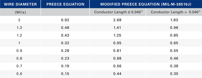
where i is the DC or RMS current, k is a constant corresponding to wire composition, and D is the diameter of the wire in inches. For gold and copper, k = 10,244. One of this equation's limitations is that it applies only to wires in free air. Additionally, it does not consider the fact that the current carrying capability of a wire varies inversely with its length. Modified Preece equation One way to address these limitations is to modify the Preece equation with a higher value of k to reflect typical packaging processes that encapsulate the bond wire with an epoxy-based molding compound. The constant k also reflects the effect of length on the wire's current-carrying capability. The value of k for conductor length ? 0.040" for both gold and copper is 30,000 and for conductor length > 0.040" is 20,500. The equation Military specification MIL-M-38510J presents bases its current-carrying capability assessment on the modified Preece equation. Table 1 lists the calculated current-carrying capability in Amperes of both conductor types using the two versions of the Preece equation. Two limitations remain with the modified Preece equation. It produces current-carrying-capability values that are material-independent. Copper has 20% higher thermal conductivity and 30% higher electrical conductivity than gold, which should result in copper being able to carry more current than gold for a given bond wire length and diameter. The equation does not extrapolate the current carrying capacity with conductor length beyond 0.040" (about 1 mm). Most applications use wire lengths in the 2- to 3-mm range or longer. A wire's current-carrying capability varies dramatically as conductor length changes, which the equation fails to consider. Given these limitations, a new approach is necessary that accounts for known geometry and material properties and on limitations typical applications impose. Joule heating in conductors Current flowing through a non-ideal conductor—one with non-zero electrical resistance—converts electrical energy to thermal energy through a process called Joule heating or resistive heating. The magnitude of heat the processes generates is directly proportional the wire resistance and to the square of the current:
For a conductor surrounded by still air, all heat generated dissipates through the conductor with negligible heat conducted away from the conductor surface. The system reaches steady state when
The generated heat dissipates through the length of the wire using a simple conduction heat-transfer process:
where k is the wire's thermal conductivity (310 W/mK for gold and 390 W/mK for copper), A is the cross-sectional area of the wire, dT is the temperature differential at the two ends of the wire, and dx is the wire's length. Rearranging and simplifying,
where ? is the wire's resistivity (2.44x10⁻⁸ ?-m for gold and 1.68x10⁻⁸ ?-m for copper), D is the wire diameter, l is the wire length, and ?T is the temperature difference between the wire's two ends, which we assume to be a constant for a maximum current-capacity calculation. Simplifying even further,
Based on the above relationship, assuming everything else remains the same, copper should be able to handle 25% more current than gold. In most practical applications, heat does not just conduct away through the wire but also conducts away in the radial direction from the surface of the wire through the epoxy-molding compound. The combined phenomenon is complex and not subject to analysis with closed-form equations but yields using finite-element modeling software with a thermal-electric-coupled physics solver to examine the effects of different wire parameters.
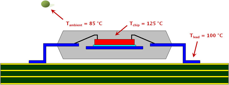
Model setup A typical wire-bond process connects the chip's I/O pads to the package's leads with wires, predominantly gold or copper (Figure 1). Manufacturers limit the IC's maximum-ambient operating temperature to 70 °C for commercial applications; 85 °C for industrial uses. Most devices specify a 125 °C maximum chip-junction temperature. To estimate the bond wires' current-carrying capacity under worst-case conditions, the models assume the industrial ambient temperature with the maximum chip junction temperature. Natural convection boundary conditions apply to the package surface, with the package lead temperature at 100 °C. A small amount of current through the wire does not change the temperature profile across the span of the wire with the two ends still at the original temperature. As the current increases, the hottest temperature is no longer at the chip junction, but is somewhere in the middle of the wire span. The glass transition temperature, Tg, of the mold compound is the temperature at which the material transitions from a hard and relatively brittle state to a soft, rubber-like one. A typical Tg is about 150 °C. If the current causes the mold-compound temperature to exceed Tg, time and temperature will degrade the epoxy's chemical bonds at this interface. This not only causes an increase in the thermal resistance of the mold compound, but also results in an increase in the porosity of the material, exposing it to the ingression of moisture and ionic contaminants. A wire-mold-compound interface temperature of 150 °C is, therefore, the upper temperature limit to calculate bond wire current-carrying capability.
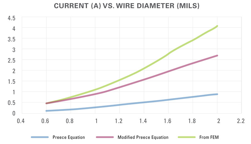
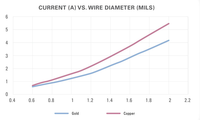
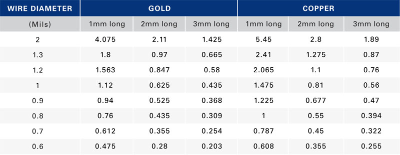
With this as the criterion, the effects of wire-material type, wire length, and wire diameter are calculable and a comparison is possible to the theoretical estimates. Figure 2 shows the current-carrying capability of 1-mm-long gold wire using the three approaches. The current value using FEM starts out at about the same level that the modified Preece equation gave but then diverges as the wire diameter increases. The FEM analysis shows the current-carrying capability of gold and copper wires modeling 1-mm-long bond wires (Figure 3) and wires of several lengths (Table 2).