Smart energy management requires intelligent feedback
Energy is often defined as the amount of power consumed over time, measured in joules (J) or kilowatt-hours (kWh), whereas power is a constant rate of energy usage, measured in watts (W). Thus, while a power rating is typically used to indicate how much electricity a device will consume at a snapshot in time, energy confirms in hindsight how much electricity was actually consumed during a defined time period. So, while the “green” goal of an energy and power monitor may ultimately be the same, an energy monitor may be more useful in most applications, since it goes a step further by accounting for shifts in power levels over time.
With AC loads aside, energy monitoring is becoming more popular and is already established in a handful of DC load applications. Handheld, rack mounted and in-line energy meters are widely available and can be used by people like facility managers to track and allocate energy used by equipment or departments among many things. This may also include load profiling, where expected energy consumption patterns are compared to present usage and areas of concern are flagged based on deviations from modeled energy patterns.
By sizing loads, users can determine how many lights, computers, batteries, etc. can be connected to a system at any time. Energy monitoring also has obvious usage in renewable energy applications, such as in the case of wind turbines or solar panels, and monitoring how much DC electricity is being generated. Similarly, electric bikes and vehicles can report energy use per mile and quantify the energy being extracted from or returned to a battery.
Although a discrete energy monitoring solution can be built using a microprocessor and a handful of other components, this incurs system overhead from continuous data polling to perform the calculations and analyze the data. A respectable energy monitoring IC provides a simple solution that alleviates the host of these burdensome tasks, where the combination of measured parameters, which include voltage, current, power and energy levels, provide instant insight into a system’s health. Programmable threshold alerts may be all that is needed to provide early detection of a fault so preventative action can be taken before catastrophic events occur. Alternatively, systems can be optimized by simply understanding usage patterns; with this kind of information, valuable resources can be diverted accordingly, where over-utilized widgets can offload tasks to underutilized widgets.
The energy monitor role model
Energy monitors can be built in many different ways, which isn’t surprising considering that a variety of components are necessary to monitor energy usage in a system. To measure current, a sense resistor and amplifier are needed, and it is most convenient if the amplifier common-mode range extends to the positive supply rail and translates its output to ground. Precision resistive dividers are needed to measure voltage and, if there is more than one voltage to monitor, a multiplexer must also be added to the list.
A multichannel analog-to-digital converter (ADC) comes next, with a precise reference and some means of interfacing to a microprocessor, while perhaps sharing I/O lines with neighboring ICs. ADC conversions would need to be synchronized to the time base of the microprocessor so that time can be tracked. The microprocessor must also multiply voltage and current to obtain power calculations, and sum these power values over the period for which energy is to be calculated.
If detection of minimum and maximum values or alerts are required for any of the parameters, additional code needs to be written and constantly executed. Because of the overall complexity and difficulty of finding suitable components, energy monitoring easily lends itself to an integrated solution.
High level of integration
By integrating all of the necessary functional blocks in a small 4mm x 3mm QFN or MSOP package, a device such as Linear Technology’s LTC2946 makes energy monitoring very practical for a wide variety of applications where a discrete solution is out of the question due to space, complexity or cost. The LTC2946 operates on as little as 2.7V, but can monitor the voltage and current of any 0V to 100V rail, as well as its own supply voltage and one additional voltage input. An on-board shunt regulator provides support for supplies greater than 100V.
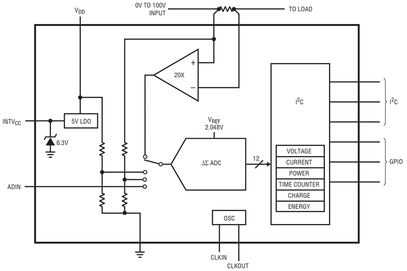
For flexibility, the sense resistor is external, allowing the LTC2946 to accurately monitor currents ranging from milliamps to tens of amps or more. The ADC has 12-bit resolution and a maximum total unadjusted error (TUE) of 0.4% for voltage and 0.6% for current. The additional ADC input (ADIN pin) TUE is also just 0.3% and can be used for monitoring auxiliary functions. The LTC2946 also integrates a digital multiplier to calculate a 24-bit power result, as well as an accumulator and oscillator to calculate 32-bit energy and charge results. All values, measurements, status and user configuration data are stored in I2C accessible registers (see Figure 1).
Click image to enlarge
Figure 1 – Simplified LTC2946 Block Diagram
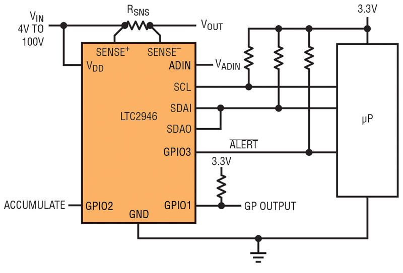
A device like the LTC2946 can find its way into many complex, space-constrained, applications including RAID systems, telecommunications, transportation, solar monitoring systems, and industrial computer/control systems. Fortunately, only a few simple connections need to be made to this device. Figure 2 shows the LTC2946 monitoring the input voltage and current of a 3.3V microprocessor, while being powered by 12V. The only required external components are a sense resistor and three pull-up resistors.
Click image to enlarge
Figure 2 – LTC2946 High Side Energy Meter
Because of the wide rail-to-rail operating range, the LTC2946 is useful in many different low voltage and high voltage systems. Not only do 100V abs-max-rated supply and sense pins provide a lot of headroom, such as in 48V or -48V applications, but the zero volt sense monitoring capability is just as useful in monitoring current levels during short circuit or blackout situations. Fault current levels at zero volts can immediately indicate whether the power supply or load has gone bad without additional circuitry.
The internal 12-bit Δ∑ADC inherently averages input noise over the measurement window, so operating in noisy environments is not a problem. In scan mode, the ADC continuously monitors the differential sense voltage, supply or positive sense voltage, and spare ADC input voltage sequentially with 25µV, 25mV and 0.5mV resolution respectively. Conversions have an effective refresh rate of up to 20Hz in continuous scan mode (depending on how often internal calibration is performed), although users can also enter a snapshot mode to take measurements of a single selectable input. In applications where conserving energy is the goal, high voltage monitoring ICs are usually expected to have high quiescent currents and therefore not usable in the application; however, the LTC2946 only consumes 0.9mA when monitoring a 48V rail and can be shut down to reduce power consumption to only 15µA.
Energizing the energy monitor
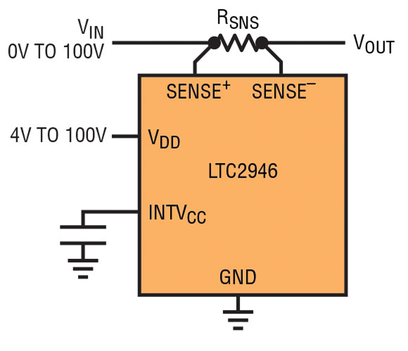
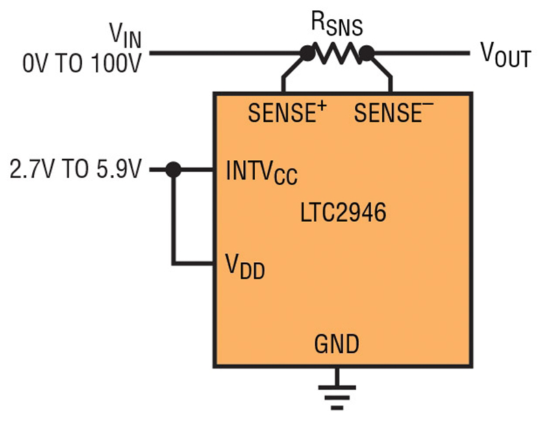
The LTC2946 can derive its power from a wide range of supplies, which drastically simplifies the design process for any application. Figure 3a shows the LTC2946 being used to monitor a supply that ranges from 4V to 80V. No secondary bias supply is needed since the VDD supply pin can be connected directly to the monitored supply. If the LTC2946 is used to monitor a supply that goes as low as 0V, it can derive power from a wide range secondary supply connected to VDD as shown in Figure 3b. Similarly, if a low voltage supply as low as 2.7V is present, the LTC2946 can be configured as shown in Figure 3c to minimize power consumption.

Clcik image to enlarge
Figure 3a) LTC2946 Derives Power from the Supply Being Monitored
Click image to enlarge
Figure 3b) LTC2946 Derives Power from a Wide Range Secondary Supply
Click image to enlarge
Figure 3c) LTC2946 Derives Power from a Low Voltage Secondary Supply
For supplies greater than ±100V, the on-board linear regulator at the INTVCC pin can be used in both high and low side configurations to provide power to the LTC2946 through an external shunt resistor. Figure 4a shows a high side power monitor with an input monitoring range beyond 100V in a high-side shunt regulator configuration. The LTC2946 ground is separated from the circuit ground through RSHUNT and clamped at 6.3V below the input supply.
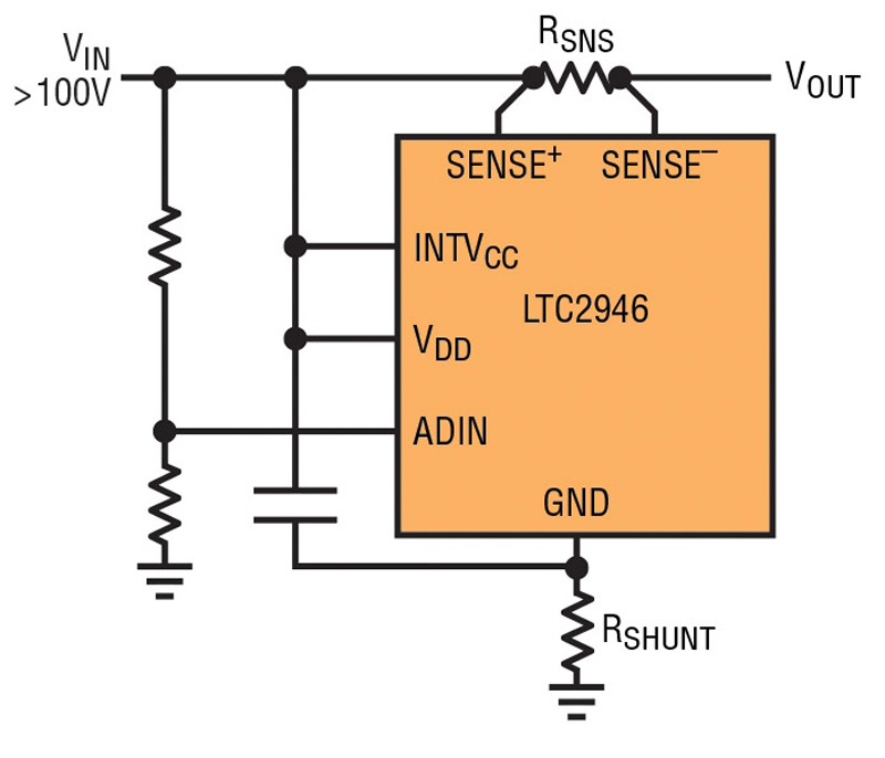
Click image to enlargr
Figure 4a) LTC2946 Derives Power Through High-Side Shunt Regulator
Due to the different ground levels, the LTC2946’s I2C signals would need to be level shifted for communication with other ground referenced components; a current mirror would also be needed to measure the external voltage on the spare ADC input. Figure 4b shows the LTC2946 deriving power from a greater than -100V supply. Here, the low-side shunt regulator configuration allows operation by clamping the voltage at INTVCC to 6.3V above the input supply, which in this case is a negative rail. As shown in figure 4c, a shunt resistor is not required if the input supply and transients are limited to below -100V, where VDD measures the supply voltage at circuit ground with respect to the LTC2946 ground.
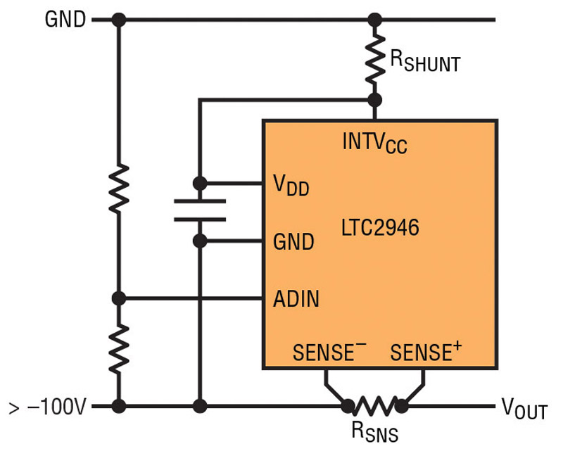
Click image to enlarge
Figure 4b) LTC2946 Derives Power Through Low-Side Shunt Regulator in Low-Side Current Sense Topology
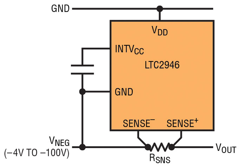
Click image to enlarge
Figure 4c) LTC2946 Derives Power from the Supply Being Monitored in Low-Side Current Sense Topology
Digital convenience
Consistent with the flexible powering options, the LTC2946 includes a host of convenient digital features that simplifies designs. The most apparent digital feature is the integration of a digital multiplier and accumulator, which provides users with 24-bit power and 32-bit energy and charge values, alleviating the host of polling voltage and current data and performing extra computations.
The LTC2946 calculates power by multiplying 12-bit measured current with 12-bit measured voltage. In continuous mode, the differential sense voltage is measured to obtain the load current data. However, the voltage data can be selected between the supply voltage, positive sense voltage, or spare ADC input voltage. A 24-bit power value is then calculated every time a current measurement is made. Lastly, energy and charge accumulators are incremented with power and current data and capable of storing several months’ worth of data at nominal current and power levels.
The LTC2946 has minimum and maximum registers for current, voltage, and power, which eliminate the need for continuous software polling and free the I2C bus and host to perform other tasks. In addition to detecting and storing min/max values, the LTC2946 has min/max limit registers that can be used to issue an alert in the event any of the limits are exceeded, again, eliminating the need for the microprocessor to constantly poll the LTC2946 and analyze data.
The LTC2946 can also be configured to generate an overflow alert after a specified amount of energy or charge has been delivered or when a preset amount of time has elapsed. For an energy monitor, an alert response can be equally as valuable as minimum and maximum registers. Figure 5 shows how the LTC2946 generates an alert signal via software and hardware.
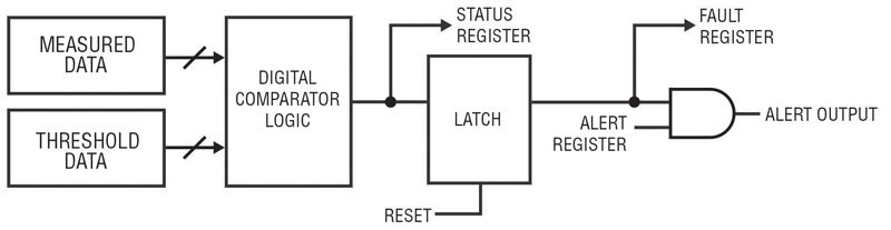
Clcik image to enlarge
Figure 5) LTC2946 Fault Alert Generation
Measured data is compared against user defined thresholds; overvoltage, undervoltage, overcurrent, undercurrent, overpower, and underpower thresholds can all be defined and simultaneously monitored. Then, a status register informs the user which parametric thresholds have been exceeded, while actual fault values are logged in another register and can be interrogated at a later time. A separate alert register allows users to select which parameters will respond in accordance with the SMBus alert response protocol, where the Alert Response Address (ARA) is broadcasted and the /ALERT pin is pulled low to notify the host of an alert event.
The LTC2946 uses a standard I2C interface with very unique enhancements to communicate with the outside world. Nine I2C device addresses are available so multiple LTC2946s can be easily designed into the same system. All LTC2946 devices respond to a common address, which allows the bus master to write to several LTC2946s simultaneously, regardless of their individual address. A stuck-bus reset timer resets the internal I2C state machine to allow normal communication to resume in the event that I2C signals are held low for over 33ms (stuck bus condition). A split I2C data line conveniently eliminates the need to use I2C splitters or combiners for bidirectional transmission and receiving of data across an isolation boundary. Furthermore, the LTC2946-1 option has an inverted data output for use with inverting opto-isolator configurations.
A simple solution
The LTC2946 is a versatile board level energy monitor that addresses a wide range of applications, providing users with a simple, yet very effective method to monitor current, voltage, power, energy, charge and time. High performance building blocks allow the LTC2946 to monitor 0V to 100V positive and negative rails with ease and at the highest level of accuracy in its class. Users have a variety of biasing options thanks to independent high voltage monitoring and supply pins, and an onboard regulator to support beyond 100V supplies. The LTC2946’s analog prowess is equally matched by its host resource-reducing digital features, including a multiplier, accumulator, min/max registers, configurable alerts and a very capable I2C interface.