Extending battery life in wireless medical devices
Key to the rapid growth of wearables is reduced device size and longer battery life
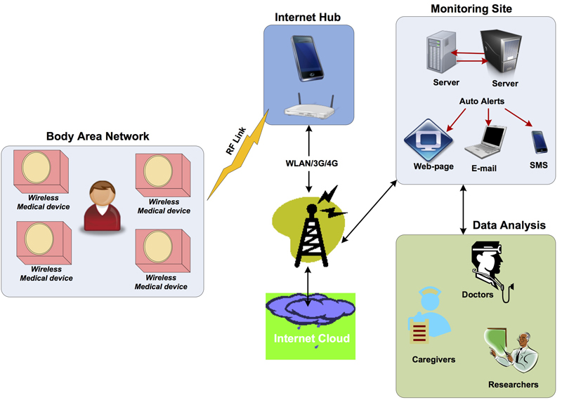
Wireless medical devices are becoming increasingly more prevalent for remotely monitoring and logging vital signs to assist in the detection and treatment of diseases and medical anomalies. An example is shown in Figure 1. Wireless body sensors upload vitals via an Internet hub or personal server such as the patient’s smart phone. To continuously monitor and upload vital data, wireless medical devices need to maintain long-term connectivity to the cloud. Key to continued rapid growth of medical wearables is reduced device size, longer battery life and ubiquity of smart phones.
Click image to enlarge
Figure 1: U-Healthcare system overview
Wearable medical monitoring devices are designed to collect and compress data (metadata), send it to the cloud via Internet hub devices in short bursts, and then go to sleep to conserve power. Battery life depends in part on the power consumption of the wireless radio and interface protocol deployed in the design. Designers of wearable sensor devices can choose from the following PAN (Personal Area Network) low power wireless communication standards:
• ANT
• ZigBee
• Bluetooth® low energy (BLE)
Which wireless protocol should the designers of such wireless medical devices deploy? See the sidebar for more information on how these protocols meet wireless requirements.
Which Wireless Standard has the Lowest Power?
Independent studies comparing the top three wireless standards have shown that BLE has the lowest power consumption in a cyclic sleep scenario typical of a network of wireless body sensors [1], [2]. The cyclic sleep scenario is a typical use case of these battery powered devices wherein the device core is shut down for a pre-set time called “sleep time” typically in the range of 2 to 10 seconds and “woken” when it needs to transmit vitals during a short burst lasting a few milliseconds. This translates to a low duty cycle activity scenario, which leads to lower average power consumption.
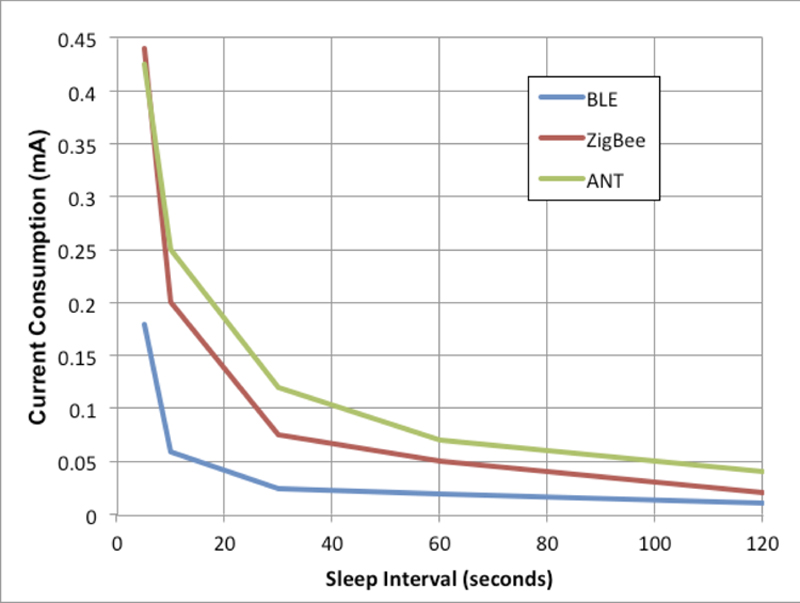
In one experiment, average power consumption was measured across various sleep intervals on three wireless modules [1]. The results of the power consumed across the various RF modules, shown in Figure 2, indicate that the BLE protocol consumes the least amount of power compared to ANT and ZigBee irrespective of sleep intervals. The data also show power consumption scales inversely with sleep interval across all three RF standards in a cyclic sleep activity scenario.
Click image to enlarge
Figure 2: Power consumption of the three wireless standards vs. sleep interval
Given the ubiquity of the smart phone and its native support for Bluetooth 4.0, BLE is ideally suited for wearable medical devices. In certain medical environments, where smart phone use is prohibited, the use of a BLE-to-Internet bridge may be used as an alternative.
BLE in a Medical Device
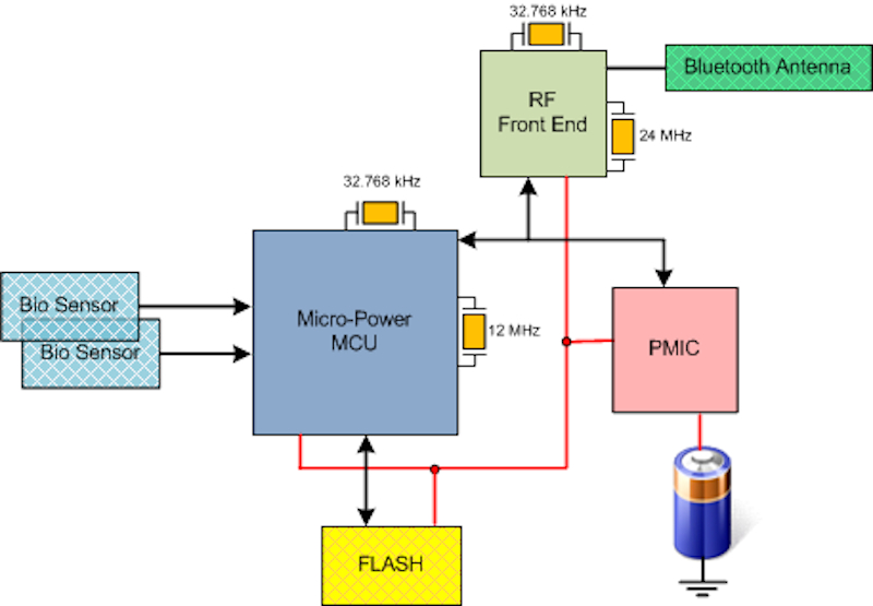
A typical wireless medical device comprises a low power 32-bit MCU interfacing to biometric sensors and a RF front-end SoC (system on chip) as shown in Figure 3. The low power MCU typically serving as sensor data aggregator sends vitals to the BLE RF front-end via an I2C or UART interface, and runs off the following clock sources:
-12 MHz crystal
-Frequency tolerance: +/- 30 ppm for 0 to 70°C
-Used for clocking ARM Cortex-M3 core and peripherals
-32.768 kHz crystal
-Frequency tolerance: -200 ppm for 0 to 70°C
-Used for real-time clock(RTC) and watch-dog timer
Click image to enlarge
Figure 3 Block diagram of a wireless medical device
The BLE RF front-end implements the Bluetooth-4.0 PHY layer and BLE Link-layer including GATT profiles (glucose, temperature, blood pressure, etc.) and runs off of two clock sources:
-24 MHz crystal
-Frequency tolerance: +/- 20 ppm for 0 to 70°C
-Used for base-band processing and RF 2.5 GHz synthesis
-32.768 kHz crystal
-Frequency tolerance: -200 ppm for 0 to 70°C
-Used for sleep clock timing
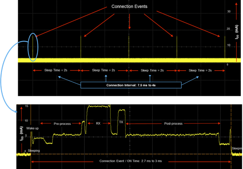
Empirical measurements have shown power consumption of a BLE medical device is inversely proportional to the time it spends in the “sleep” state, and the sleep clock accuracy (SCA) of the 32 kHz clock used to time this “sleep” state has a direct impact on the battery life of the device. To understand this, let’s briefly review how a BLE slave (patient’s medical device) and a “paired” BLE master (internet hub) establish a connection event. A scope capture of the dynamic IDD timing of a BLE slave is representative of the connection event timing profile of a BLE device as shown in Figure 4.
Click image to enlarge
Figure 4: Connection event Timing Profile of a TI CC2541 BLE SoC with IDD current scope measurements
Note that the BLE standard calls out “sleep time” by the term “connection interval”; range: 7.5 ms to 4s. The connection event is the “ON” time during which certain functional blocks of the device wake up and stay active for short periods in the range from 0.08 ms to 1.3 ms.
The following link parameters are negotiated by the BLE slave with the BLE master during every connection event:
-Connection interval (sleep time)
-Sleep latency
-Supervisory timeout
A sleep latency value of N (N < 500) extends the sleep time by N connection intervals. Example: connection interval = 2 s and sleep latency = 5 extends the sleep time to 2 x 5 = 10 seconds. The link parameter, supervisory timeout is used by the master to terminate the connection if a “paired” slave does not respond within an agreed upon time period; range: 100 ms to 32 s.
To further understand the impact of the 32 kHz sleep clock accuracy (SCA) let’s review the link-layer (LL) messages exchanged between a “paired” master and slave device while establishing a connection event.
During every connection event, the master sleep clock accuracy (master SCA) is communicated to the slave. The slave determines when to wake up during consecutive connection events based on a combination of the following:
-Last negotiated connection interval
-Master SCA
-Its own sleep clock accuracy (slave SCA)
Due to inaccuracies of the sleep clocks involved, there’s a certain level of uncertainty in the time when the slave wakes up from sleep to listen to packets from the master. Due to this uncertainty, the slave wakes up and starts listening (receiver turned ON) earlier – a process called “window widening”. As per the Bluetooth 4.0 specification volume 6, this window widening or early turn on time, ΔT is given by the following formula:
ΔT = windowWidening = ((masterSCA + slaveSCA)/1000000)*(last connection interval))
Where:
-masterSCA is sleep accuracy of the master 32 kHz sleep clock in ppm
-slavesSCA is sleep accuracy of the slave 32 kHz sleep clock in ppm
-last connection interval is the last successful established connection interval in seconds
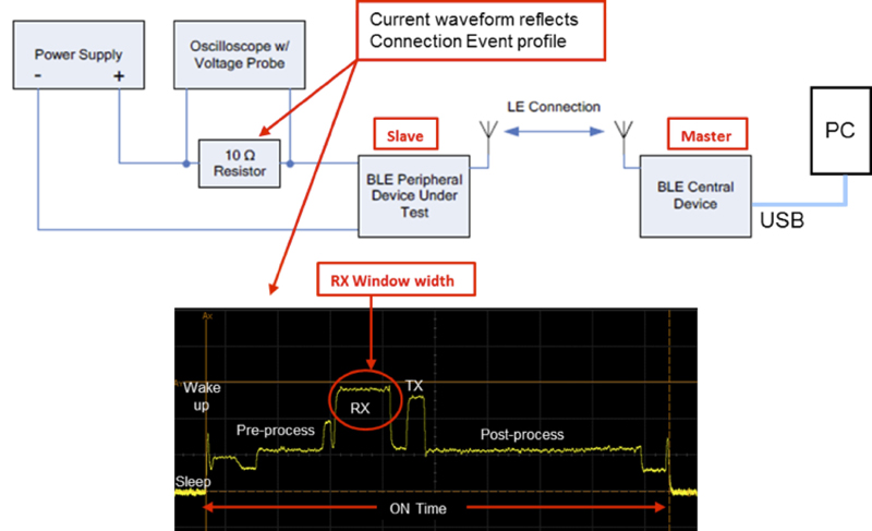
This “window widening” directly translates to the width widening of the slave RX window shown in Figure 5. In order to quantify the RX window width across various SCA settings, we measured the current profile of a BLE slave in a test setup similar to the one referenced in the TI BLE Application Note [3].
Click image to enlarge
Figure 5: Measuring RX Window width on a BLE Slave with varying sleep clock accuracies
The link parameters programmed in to the slave:
-Connection Interval = 2 s
-Latency = 0
-Supervisory timeout = 32 s
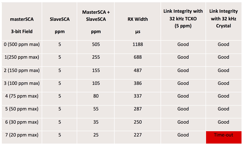
The 32 kHz crystal on the BLE slave was replaced with a high accuracy 32 kHz 5 ppm TCXO (SiT1552 from SiTime); slaveSCA = 5 ppm. A vendor provided GUI was used on the host PC to sweep the masterSCA values: 20 to 500 ppm in eight steps. For each masterSCA setting, the RX width during a connection event (ON time) was measured.
The RX width measurements listed in Table 1 correlate with the equation for window widening – width increases proportionately as the combined SCAs.
Click image to enlarge
Table 1: Impact of sleep clock accuracy (SCA) on the width of slave RX window
Extending Battery Life
Due to the use of micro-power MCUs which turn on during short bursts of a few milliseconds, most of the system power during ON time is dictated by the BLE RF front-end in a wireless medical device. As explained earlier, 32 kHz sleep clock inaccuracies cause the BLE radio receiver (RX) to turn on earlier and stay on longer to avoid missing packets from the master whereby increasing the power penalty.
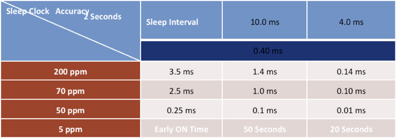
Table 2 shows that tighter slave clock accuracy reduces early ON time, ΔT thereby reducing power consumption. Let’s compute battery life extension ratios for two distinct 32 kHz sleep clock accuracies.
-TON = 3 ms (typical)
-for 5 ppm sleep clock (SCA = 5) and 20 seconds sleep time, ΔT1 = 0.1 ms
-for 200 ppm sleep clock (SCA = 200) and 20 seconds sleep time, ΔT2 = 4.0 ms
Click image to enlarge
Table 2 Tighter slave clock accuracy reduces early ON time
Device power dissipation is directly proportional to total ON time (ΔT + TON). Battery life extension ratio is inversely proportional to device power dissipation:
P2/P1 = (ΔT2 + TON)/(ΔT1 + TON) = 2.26 times
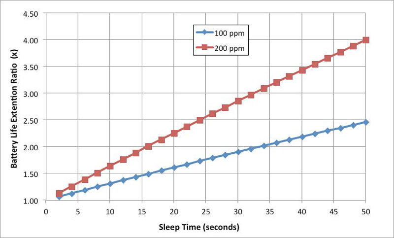
The plot in Figure 6 shows the achievable battery life extension with a 5 ppm sleep clock over a 70 ppm and 200 ppm 32 kHz clock source. For instance, for a sleep interval = 20 seconds a 5 ppm 32 kHz sleep clock can achieve > 2x battery life extension over a 200 ppm sleep clock.
Click image to enlarge
Figure 6: Battery life extension ratio with a 5 ppm 32KHz TCXO over a 100 ppm and 200 ppm XO
Power Optimized Medical Devices
Designers of wearable medical devices now have an alternative higher accuracy 32 kHz sleep clock to accurately wake-up after extended sleep times with optimized radio RX window widths.
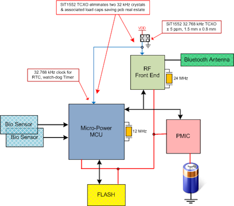
In practice, a small form factor (1.5 x 0.8 mm) 32.768 kHz TCXO, such as SiTime’s MEMS-based SiT1552 with a +/- 5 ppm frequency tolerance across -40° to 85°C is available as an alternative to the 200 ppm 32 kHz crystal-based sleep clock sources used in past designs[4]. An optimized version of the medical device architecture using the SiT1552 TCXO is shown in Figure 7. The SiT1552 TCXO can drive multiple CMOS loads and is shown eliminating both the bulky BLE sleep clock crystal and the MCU RTC 32 kHz crystal, saving precious board real estate. Designers can now leverage compression and transmit vitals in short bursts only when requested while keeping the device in its lowest power sleep state for extended periods and potentially achieving up to twice the battery life extension.
Click image to enlarge
Figure 7: Optimized architecture of a medical device using SIT1552 TCXO in lieu of traditional 32 kHz crystals
References
[1] A. Dementeyev, S. Hodges, S. Taylor and J. Smith, "Power Consumption Analysis of Bluetooth Low Energy, ZigBee, and ANT Sensor Nodes in Cyclic Sleep Scnerio," in IWIS, Austin, 2013.
[2] R. Tabishi, M. B. Adel and F. G. A. Taouti, "A Comparative Analysis of BLE and 6LoWPAN for U-healthcare Applications," IEE GCC, Quatar, 2013.
[3] Texas Instruments, "AN092 : Measuring Bluetooth® Low Energy Power Consumption," TI, Dallas, 2012.
[4] SiTime Corp, "SiT1552 Data Sheet," www.sitime.com/products/datasheets/sit1552/SiT1552-datasheet.pdf SiTime Corp, Sunnyvale, 2014.