Factory Calibrated Configurable IO-Module Brings the Wiring Cabinet to You

Modern industrial networks now support advanced protocols that allow real-time remote monitoring and configuration of sensors on the factory floor
Figure 1: Technician adjusting connections at wiring closet
Connecting sensors and actuators to a process controller at the wiring cabinet is still a manually intensive and sometimes frustrating task. For example, if a process modification means a valve being driven by a Digital Output (DO) voltage must be changed to one using a 4-20mA Analog Output (AO) current, a technician must visit the wiring cabinet and physically move the valve connections from a DO channel to an AO channel, either by routing the wiring to a different IO module or by changing the IO card (if a rack type module is being used). A similar scenario occurs if a Digital Input (DI) sensor must be changed for an Analog Input (AI). While automation engineers select IO modules to have sufficient channels (allowing for some redundancy) at the commissioning stage of a new process, the continuous addition of sensors and actuators can mean that, over time, there are fewer spare channels available, potentially leading to an awkward scenario where there are insufficient channels of a particular type to accommodate further changes. A spare DI is not much use to a technician who needs an AI channel when none are available. Adding a new (and costly) IO module may not even be possible within the confines of a tightly packed cabinet. When the requirement for different IO channel types to be periodically recalibrated is also factored in, the amount of manual intervention and associated production downtime quickly adds up.
Process automation engineers surely yearn for a universal IO channel that can be configured (and calibrated) remotely to perform any function (input or output, voltage or current) for any signal type (analog or digital) with no need for a technician to visit the wiring cabinet. In this Design Solution, we briefly revisit the main features of sensor and actuator signals used in industrial environments before introducing a new reference design that clearly signposts the path to the holy grail of the process automation engineer – the factory calibrated, remotely configurable universal IO module.
Digital IO
DI and DO signals are typically DC voltages in the range 0-24V. DIs are used to detect discrete liquid levels, for object detection or to indicate the state of a pushbutton switch. DOs are used to drive motors, actuators and to energise solenoids. These come in a variety of configurations – high-side, low-side and push-pull depending on how the load is referenced, with drive current being the main specification, ranging from hundreds of milliamps to several Amps.
Analog IO
Analog IO signals are either an electrical current in the range of 4-20mA or DC voltages typically in the range of 0-10V (although bipolar options and wider voltage ranges are available). AIs receive signals from sensors used to make precise measurement of quantities such as distance, pressure, light etc, while AOs are used to precisely control the movement and position of actuators.
Temperature
In industrial environments, temperature measurement is primarily performed using one of two types of sensors – a thermocouple (TC) or a Resistance-Temperature Detector (RTD) with 2- 3- and 4-wire variants. Thermocouples are robust, operate over a wider temperature range and are relatively inexpensive compared to RTDs which are more stable, provide higher accuracy and have better linearity. Signal output levels depend on the type of TC/RTD used and may be connected to AI channels. Robustness (as exhibited by compliance with the IEC-61000-4 transient immunity standards) is a key performance criterion for all types of industrial IO interfaces.
Universal IO Module Reference Design
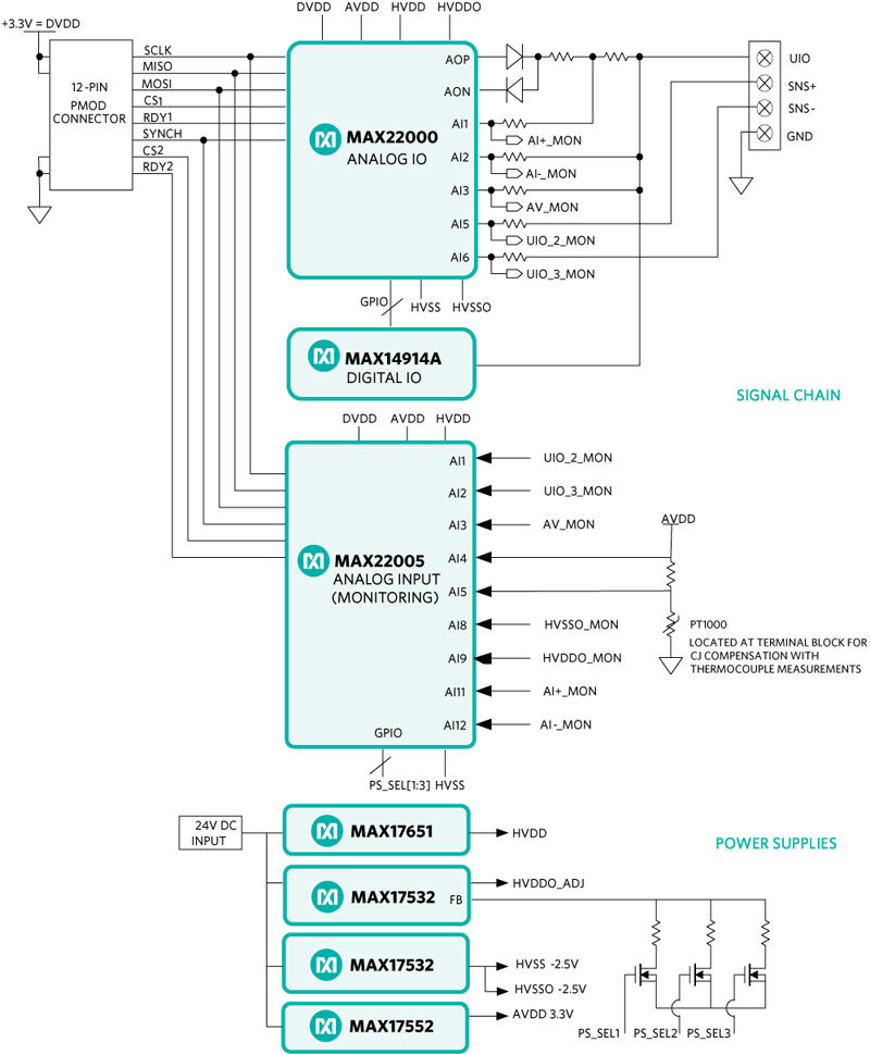
Increased integration means that in more recent IO modules, individual channels can be configured to function as either an input or an output, but the analog and digital domains remain separate. Figure 2, however, illustrates the functional diagram of a reference design for a new type of IO module in which a single universal UIO pin can be configured, using software, to function as either an AI, AO, DI, DO with respect to a single ground pin (GND).The configurable modes include analog voltage input (0 to +10V), analog current input (0 to +20mA), analog voltage output (0 to +10V), and an analog current output (0 to +20mA). It also incorporates an IEC 61131-2 Types 1, 2 or 3 compliant 0-24V digital voltage input and a push-pull/high-side digital output (capable of driving up to 1.3A of current). It also supports temperature measurements using a resistance temperature detector(RTD) and provides built-in cold-junction compensation for thermocouple measurements. The use of an industry-standard four-way PCB terminal supports UIO mode as well as 2-wire, 3-wire or 4-wire temperature measurements.
The module’s AI and AO functions are realized using the MAX22000, a software configurable analog input/output IC that can operate in either voltage or current mode. Analog output signals are generated using its internal 18-bit DAC, while the integrated 24-bit ADC has a low-noise PGA with high-voltage and low-voltage input ranges to support RTD measurements. The DI and DO functions are realized using the low-leakage MAX14914A, a high-side/push-pull driver that can also be configured to operate as a DI. Apart from providing DIO functionality, the MAX14914A also monitors the output current in both high-side and push-pull mode. A logic level corresponding to the state of the DO can be polled via a GPIO on the MAX22000 GPIO, a necessary feature in safety-critical applications.
Click image to enlarge
Figure 2: Functional diagram of the MAXREFDES185# Universal IO Module Reference Design
Software Configuration
The module uses an industry-standard 12-way Pmod connector popular on many microcontroller and FPGA platforms. For easy testing the module can be configured via a software GUI with a USB-to-SPI adapter, such as the USB2PMB2#, providing the physical interface to the board. The GUI has two tabs - the Universal IO tab (Figure 3) has a drop-down menu to allow selection of analog or digital, input or output configurations. Depending upon the mode selected, the GUI displays a simplified block diagram of the internal connections to the IC which enables the currently selected function.

Click image to enlarge
Figure 3: Universal IO Tab of GUI
The Analog Input tab can be used for monitoring purposes, allowing the voltage or current signal appearing at the UIO pin to be visually compared to that being measured by the MAX22005, a 12-channel 24-bit analog input device. Hex values are also provided for easy correlation between the two ADC cores.
Calibration
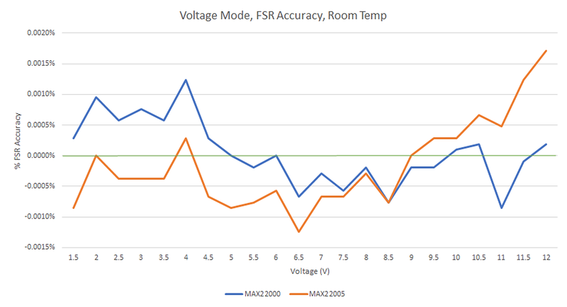
A major benefit of this module is that voltage and current calibration can be performed using the on-board MAX22005, a 12-channel, factory calibrated analog input IC that acts as a reference and also monitors analog signals present at the UIO pin. It is factory calibrated to be accurate to 0.02% FSR at 25°C and exhibits 0.05% FSR over ±50°C.Calibration is performed by clicking ‘Autocal’ on the Universal IO tab of the GUI. Figure 4 illustrates the FSR accuracy of the analog voltage signals present at the UIO pin and at the MAX22005, both comfortably outperforming the 0.02% FSR expected for precision instruments and exhibiting a high degree of correlation.
Click image to enlarge
Figure 4: Voltage measurement accuracy
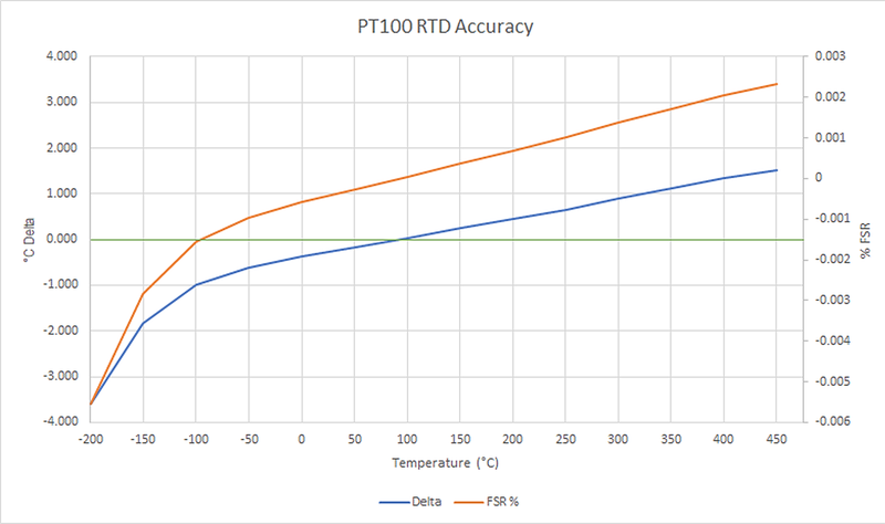
A similar level of accuracy is demonstrated for current measurement, while Figure 5 shows the accuracy of temperature readings using a Fluke 724 calibrator to emulate a PT100 RTD sensor. Accurate to within 1°C between -100°C to +300°C, it is comfortably within 0.02% FSR at room temperature. Total accuracy for the complete module is up to 0.1% FSR for ±50°C temperature variation.
Click image to enlarge
Figure 5: Temperature measurement accuracy
Power Optimization
A power tracking feature limits the amount of heat dissipated by the module. This is achieved using a combination of a low quiescent current linear regulator and high efficiency buck converters. With a quiescent current of only 8µA, the MAX17651 provides a regulated 24V supply from the DC input while the MAX17532 and MAXM17552 buck converters generate multiple analog output supply voltages, one of which is programmable to five different preset values between 4.2V and 24V. This is done using GPIO pins on the MAX22005 to switch in feedback resistors using external FETs. The module typically consumes 10mA under normal conditions, but this increases if either current input or current output mode is selected. A green LED indicates the presence of an external supply.
Robustness
While not immediately transferable to field applications in its current form, the module nonetheless exhibited a high degree of robustness when tested for the transient immunity requirements specified for industrial equipment inIEC 61131-2. It withstands up to ±1.0kV of 1.2/50µs surge with a total source impedance of 42Ω. Surge testing (line-to-line and line-to-ground) was performed using ten surge pulses,with the module continuing to operate normally without damage. Data and control registers on the device ICs were not corrupted and communication via the host adapter was uninterrupted.The module was also found to withstand electrostatic discharge (ESD) up to ±4kV port-to-ground, for contact and airgap discharge, when tested at the field connection terminal block. No damage was observed, and host communication continued normally after testing. The front view of the module, which has a tiny 75mm x 20mm form factor is shown in Figure 6.

Click image to enlarge
Figure 6: MAXREFDES185# Reference Design
Figure 7 clearly demonstrates the flexibility and space-saving benefits of choosing a single universal IO module (UIO) that can perform four separate functions, which can be configured and calibrated remotely using software, to replace several standard modules, each performing only a single function and requiring manual configuration and calibration.

Click image to enlarge
Figure 7: One universal IO module replaces several standard modules
Summary
Industry 4.0 requires industrial equipment with maximum adaptability and flexibility. The requirement to manually rewire and calibrate IO interfaces has so far been a limiting factor in this regard. The MAXREFDES185# remotely configurable IO reference design now provides a clear roadmap for future IO modules to provide ultimate flexibility and configurability. Apart from IO modules, this reference design and its component ICs are also suitable for applications in PLC and DCS systems, smart sensors and actuators.