Author:
Jonathan Colao, Applications Engineer, Analog Devices
Date
10/28/2021
 PDF
PDF
Click image to enlarge
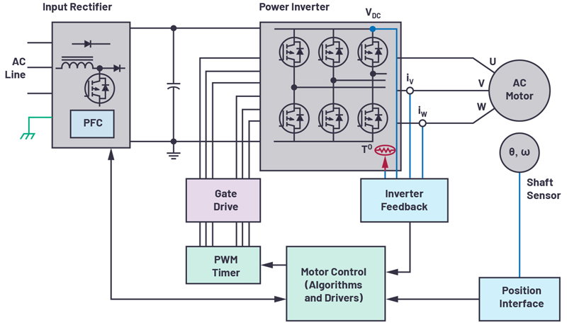
Figure 1. Closed-loop motor control feedback system
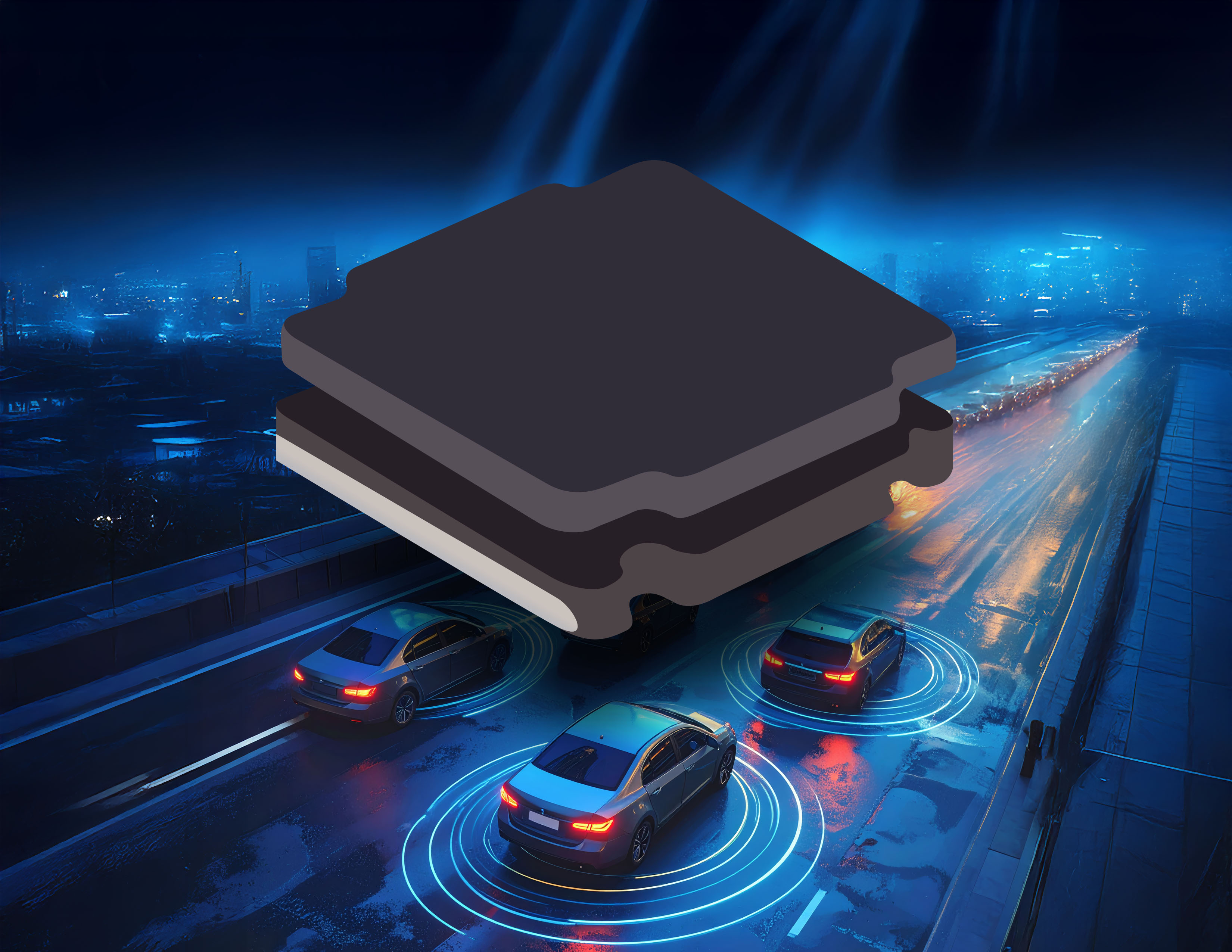
Motor rotation information such as position, speed, and direction must be accurate in order to produce precise drivers and controllers across a wide variety of emerging applications—for example, in pick-and-place machines that mount microscopic components in the limited PCB area. Recently, motor controls have been miniaturized, enabling new applications in surgical robotics for healthcare and in drones for aerospace and defence. The smaller motor controllers also enable new applications in industrial and commercial installations. The challenge for designers is to meet the high accuracy requirement of the position feedback sensor in a high speed application, while at the same time infusing all components into the limited PCB space to be fit inside tiny enclosures, such as a robotic arm.
Motor Control
Motor control loops, as seen in Figure 1, are mainly made up of a motor, a controller, and a position-feedback interface. The motor turns a rotating shaft that causes the arms of a machine to move accordingly. The motor controller tells the motor when to apply force, stop, or continue rotating. The position interface in the loop provides rotational speed and position information to the controller. This data is central to the proper operation of a pick-and-place machine for the assembly of a tiny surface-mount PCB. All these applications require accurate position measurement information about the rotating object.
The position-sensor resolution must be very high—enough to accurately detect the motor shaft position, correctly pick up a tiny component, and place it accurately on a board. Also, higher motor rotational speeds lead to higher loop bandwidth and lower latency requirements.
Position-Feedback System
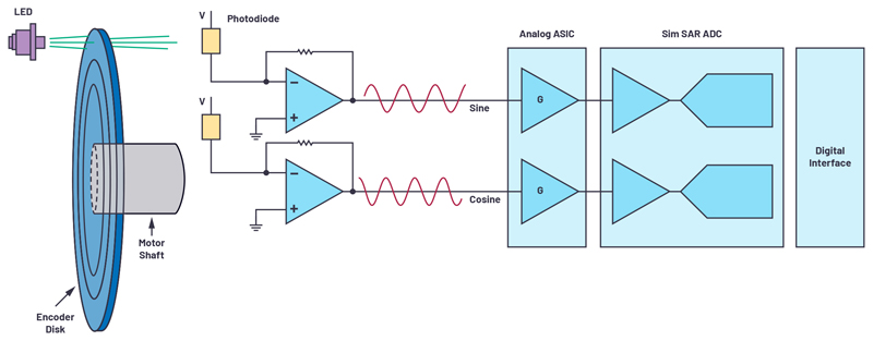
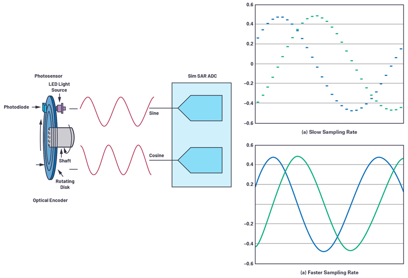
In a lower end application, an incremental sensor along with a comparator may suffice for position sensing, while a higher end application will require more complex signal chains. These feedback systems comprise the position sensor, followed by analog front-end signal conditioning, the ADC, and its driver before data gets into the digital domain. One of the most precise position sensors is the optical encoder. An optical encoder is composed of an LED light source, a marked disc attached to the motor shaft, and a photodetector. The disc features a masked pattern of opaque and transparent areas that obscure the light or allow it to pass through. The photodetectors sense the resulting light and the on/off light signals are converted to electric signals.
As the disc turns, the photodetectors—in conjunction with the patterns of the disc—produce small sine and cosine signals, in the mV or µV level. This system is typical in an absolute position optical encoder. These signals are fed to an analog signal conditioning circuitry, usually consisting of a discrete amplifier or an analog PGA to gain the signal up to the 1 V p-p range—commonly to fit an ADC input voltage range for maximum dynamic range. Each of the amplified sine and cosine signals are then acquired by a simultaneous sampling ADC’s driver amplifier.
Click image to enlarge
Figure 2. Position-feedback system
The ADC must feature simultaneous sampling on its channels such that the sine and cosine data points are taken at the exact same point in time, as that combination provides the shaft position information. The ADC conversion results are passed to an ASIC or microcontroller. The motor controller queries the encoder position every PWM cycle and uses this data to drive the motor based on the instructions it receives. In the past, system designers would have to trade ADC speed or channel count to fit restrictive board footprints.
Optimizing Position Feedback
The demands of evolving technology have resulted in innovation in motor control applications that require high accuracy position detection. The optical encoder resolution can be based on the number of slots inscribed from fine lithography in a disc, usually hundreds or thousands. Interpolating these sine and cosine signals to a high speed, high performance ADC will enable us to create higher resolution encoders without requiring system changes to the encoder disc. For example, when an encoder sine and cosine signal are sampled at a slower rate, fewer values of the signal are captured, as shown in Figure 3; this also limits the accuracy of the position cap. In Figure 3, when the ADC samples at a faster rate, more detailed values of the signal are captured, and a higher accuracy position is determined. A high speed sampling rate of the ADC allows oversampling, further improving the noise performance, removing some digital postprocessing needs. At the same time, it reduces the output data rate from the ADC; that is, allowing for slower serial frequency signals, hence simplifying the digital interface. The motor position-feedback system is mounted in the motor assembly, which can be pretty small in certain applications. So size is vital to fit in the limited PCB area of the encoder module. The emerging of multiple channel components in a single, tiny package are best suited for space saving.
Click image to enlarge
Figure 3. Sampling rate
Optical Encoder Position-Feedback Design Example
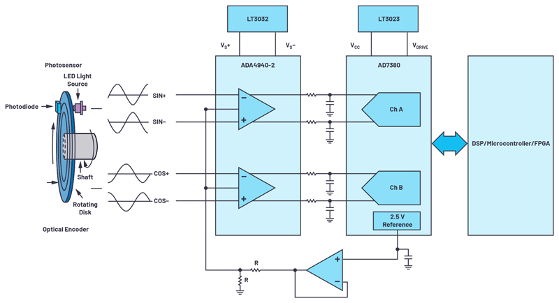
An example of an optimized solution for an optical encoder position-feedback system is shown in Figure 4. The circuit can be easily interfaced to an absolute type of optical encoder where differential sine and cosine signals from the encoder can be easily captured by the circuit. The ADA4940-2 front-end amplifier is a dual-channel, low noise, fully differential amplifier that drives the AD7380, a dual-channel, 16-bit, fully differential, 4 MSPS, simultaneous sampling SAR ADC, housed in a small 3 mm × 3 mm LFCSP package. The on-chip 2.5 V reference would allow minimum component requirements for this circuit. The VCC and VDRIVE of the ADC and the supply rails of the amplifier driver can be powered by an LDO regulator, such as the LT3023 and LT3032. When these reference designs are interfaced—for example, with a 1024-slot optical encoder that produces 1024 cycles of sine and cosine in one revolution of the encoder disc—the 16-bit AD7380 samples each encoder slot at 216 codes, overall increasing the encoder resolution up to 26 bits. The 4 MSPS throughput rate ensures that detailed sine and cosine cycles are captured and encoder positions are up to date. The high throughput rate enables oversampling on-chip, which reduces the time penalty of digital ASICs or microcontrollers feeding the precise encoder position to the motor. An extra benefit of the AD7380’s on-chip oversampling is that it allows for an additional 2 bits of resolution, which can be easily used with an on-chip resolution boost feature. The resolution boost can further improve the accuracy up to 28 bits. Application note AN-2003 details this oversampling and resolution boost feature of the AD7380.
Click image to enlarge
Figure 4. Optimized feedback system design
Conclusion
Motor control system demands for higher accuracy, higher speed, and miniaturization are increasing. Optical encoders are used as motor position-sensing devices. To do this, the optical encoder signal chain must have a high level of accuracy when measuring the motor position. A high speed, high throughput ADC accurately captures information and feeds motor position data to the controller. The AD7380’s speed, density, and performance answers the industry’s demand while enabling higher levels of accuracy and optimization in the position-feedback system.