Flexible algorithm development, accurate supply monitoring, and rapid fault logging enhance product reliability.
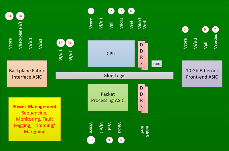
Figure 1: Communication line card primary ICs and power supply requirements
- The number of power supplies on a board depends on the VLSI chip complement, the communication speed between them, and the number of other devices that require unique supplies.
- Adjust the time delay between turning on each of the rails or rail groups.
- Rearrange the supply turn-on sequence.
- Set the supply turn-off sequence.
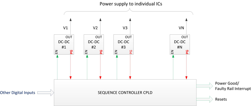
Implementation example One common approach to implementing complex power management is to use power-good signals from DC-DC converters to monitor the supplies and use a CPLD to implement the sequencing algorithm to controlling DC-DC converter-enable signals. The CPLD also generates supervisory signals such as power-good, faulty-rail-interrupt, and reset signals (Figure 2). This implementation brings six key advantages: It meets all sequencing requirements. It's scalable with the number of supplies. There's no limitation on the power up or power down sequencing algorithm size or complexity. The sequencing algorithm can interleave supervisory signals such as power-good or faulty-voltage indications between supply sequencing. Any number of digital inputs can control the sequencing and monitoring algorithms. In-field upgrading procedures can update the sequencing algorithm without interrupting the board operation. The implementation does, however, bring four disadvantages: An cctive power-good signal does not mean that the supply is within the client IC's supply tolerance. The power-good signals from most DC-DC converters have a monitoring error of 8 to 20% but most ICs' supply tolerances are between 3 to 5%. For example, the 1.2 V core-supply rail's voltage can be 10% below the rated value—1.08 V—but the DC-DC converter power-good signal can indicate that the supply is good and the CPLD may not activate its reset signal. Consequently, the CPU may hang and overwrite a section of the Flash memory. Systems should not use the power-good signal from a DC-DC converter as a supply rail fault indication to generate supervisory signals such as reset or low-voltage interrupt. Often this type of supervisory system with enable some ICs before their supply voltages are within operating tolerances. As a result, sequencing algorithms wait for an additional time before enabling the ICs, and the board does not start-up reliably. Increases software debug time - Due to the poor accuracy of the CPU and memory supplies' power-good signals Flash corruption can occur, increasing software-degug time. It is difficult to differentiate between a software bug and unexpected program behavior due to faulty supply. Because there is no way to determine the faulty supply in hardware, software engineers waste time blaming the software bug for Flash corruption before blaming the faulty board. This can cause a delay in product release.
Implementation example One common approach to implementing complex power management is to use power-good signals from DC-DC converters to monitor the supplies and use a CPLD to implement the sequencing algorithm to controlling DC-DC converter-enable signals. The CPLD also generates supervisory signals such as power-good, faulty-rail-interrupt, and reset signals (Figure 2). This implementation brings six key advantages: It meets all sequencing requirements. It's scalable with the number of supplies. There's no limitation on the power up or power down sequencing algorithm size or complexity. The sequencing algorithm can interleave supervisory signals such as power-good or faulty-voltage indications between supply sequencing. Any number of digital inputs can control the sequencing and monitoring algorithms. In-field upgrading procedures can update the sequencing algorithm without interrupting the board operation. The implementation does, however, bring four disadvantages: An cctive power-good signal does not mean that the supply is within the client IC's supply tolerance. The power-good signals from most DC-DC converters have a monitoring error of 8 to 20% but most ICs' supply tolerances are between 3 to 5%. For example, the 1.2 V core-supply rail's voltage can be 10% below the rated value—1.08 V—but the DC-DC converter power-good signal can indicate that the supply is good and the CPLD may not activate its reset signal. Consequently, the CPU may hang and overwrite a section of the Flash memory. Systems should not use the power-good signal from a DC-DC converter as a supply rail fault indication to generate supervisory signals such as reset or low-voltage interrupt. Often this type of supervisory system with enable some ICs before their supply voltages are within operating tolerances. As a result, sequencing algorithms wait for an additional time before enabling the ICs, and the board does not start-up reliably. Increases software debug time - Due to the poor accuracy of the CPU and memory supplies' power-good signals Flash corruption can occur, increasing software-degug time. It is difficult to differentiate between a software bug and unexpected program behavior due to faulty supply. Because there is no way to determine the faulty supply in hardware, software engineers waste time blaming the software bug for Flash corruption before blaming the faulty board. This can cause a delay in product release.
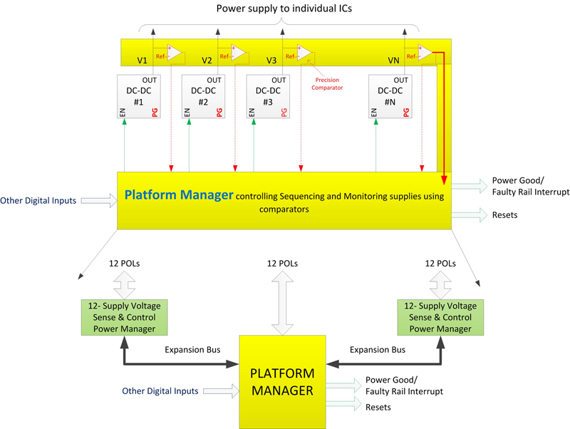
Distributed sensing and centralized control An alternative is to provide accurate remote sensing and centralized control (Figure 3). This architecture is similar to the previous circuit but, due to the integration of the comparators and ADC, it requires the least number of components. For example, a Lattice Platform Manager and two Lattice Power Manager ICs implement the arrangement and provide power management for up to 36 rails. The Platform Manager integrates 12 supply voltage monitoring, a 48 macrocell CPLD and a 640 LUT FPGA. The Power Manager can sense and control up to 12 point-of-load supplies. The FPGA section of the Platform Manager implements the overall power-management algorithm and supports supply trimming and margining. This approach brings seven advantages: It provides flexible sequencing support for up to 36 rails because the FPGA implements the central power management. There is no limit to timing adjustment or sequencing response to each of the power failure conditions. The system generates supervisory signals with no compromise to reliability because the voltage monitoring accuracy is 0.7 %. In addition, because both the Platform Manager and the Power Manger support differential voltage sensing, they don't degrade measurement accuracy due to ground-voltage differences between various areas of the PCB. Because the FPGA receives all supply-fault status signals, the algorithm responds to any fault within 100 ?s and generates the supervisory signal immediately. This speed, coupled with high monitoring accuracy, minimizes the chance of Flash corruption. The system can log any supply fault into non-volatile memory in 100 ?s. This ensures that the fault log contains the primary fault. Designers can implement the power-management algorithm using HDL code or using a simplified algorithm development tool called LogiBuilder. Engineers can simulate and fine tune the algorithm, minimizing the chances of errors that require a board re-spin. In-field upgrading procedures can update the power-management algorithm without interrupting the board's operation. The device also stores a golden image, so if an event interrupts the in-system update, power cycling the board restores the previous algorithm and the upgrade procedure can begin again. The communication between the Platform Manager and the Power Manager is simple and reference designs are available. The user simply adds the reference design to the board power-management algorithm. The reference design automatically manages the communication among all devices without intervening in the main power-management algorithm. www.latticesemi.com


