Dr. Ridley shows how the intricate details of magnetics construction can have a major impact on the operation of a flyback converter.
Flyback Transformer Primaries
If you are designing a flyback converter, it is normally for a high-voltage input, and you do not need a lot of power â�" typically 10 watts or less. Space is always at a premium, and you want to keep the transformer as small as possible.
These common constraints often lead to a design with a small core, and many primary turns, often more than 100. The use of multiple winding layers cannot usually be avoided, and a decision must be made about exactly how to arrange the multiple layers of the winding. In this article, the case of a 130-turn primary, wound in two layers on an EPC19 bobbin from TDK will be considered. Three different winding configurations were built and tested.
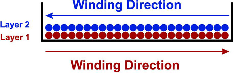
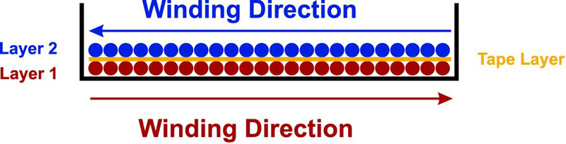
Figure 1 shows the first configuration, where a 34 awg wire is wound out and back across the bobbin with no tape between the layers. This is the most common arrangement since a low-cost winding machine can be programmed to automate this layout very easily. It is also very easy to build manually for prototyping.
Click image to enlarge
Figure 1: Flyback Transformer Two-Layer Primary with No Tape. This is the Maximum Capacitance Configuration.
Unfortunately, this is also the worst way to arrange a two-layer winding since it produces the maximum winding capacitance, and the maximum voltage stress between adjacent wires at the beginning and the end of the winding. Despite these drawbacks, most manufacturers wind this way, and most designers do not have the experience to insist on changes that can improve the performance.
Click image to enlarge
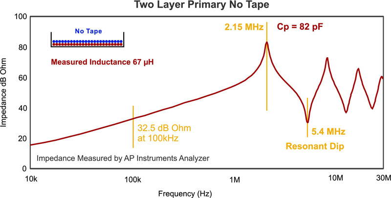
Figure 2: Primary Impedance Measurement with Maximum Capacitance Winding Configuration, Two Layers with No Tape. Equivalent Capacitance is 82 pF.
Figure 2 shows the frequency response measurement of this transformer primary winding configuration. All measurements in this article were made with the AP300 frequency response analyzer, configured to measure high impedances, and transformer capacitances as low as 2 pF.
From this frequency response curve, the inductance of the primary winding is calculated at 100 kHz to be 67 ��H. The first resonant peak in impedance occurs at 2.15 MHz, and this corresponds to a primary capacitance of 82 pF. While this may seem like a small value of capacitance, it will cause a significant leading-edge spike on the current waveform in the flyback primary.
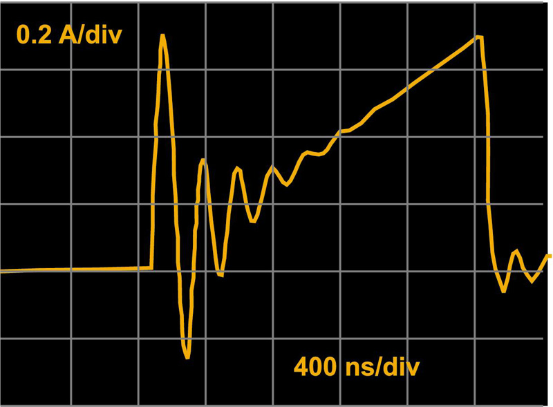
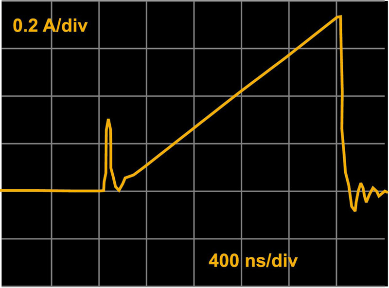
The winding arrangement also gives a dip in impedance at 5.4 MHz, and this sharp dip will result in ringing of the primary current. Both the leading-edge spike, and current ringing are shown clearly in Figure 3.
Click image to enlarge
Figure 3: Primary Switch Current with Maximum Capacitance Winding. Notice Large Initial Current Spike and Continued Ringing. Frequency of Ringing Corresponds to the Resonant Dip in the Impedance Measurement.
Waveforms like this are quite common in production power supplies. However they present problems of EMI, current-limiting precision, and protection. The waveforms can be improved by some simple changes to the primary of the transformer winding.
Flyback Transformer Primary with Tape Insulation
The high capacitance of the configuration of Figure 1 results from the very thin insulation on the windings, and the close proximity of windings with high voltage differentials. The performance of the winding can be improved by placing a layer of tape between the two layers of wire, as shown in Figure 4.
Click image to enlarge
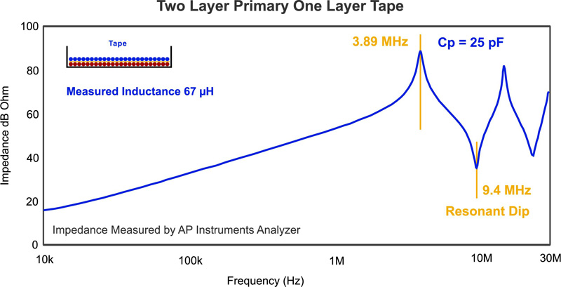
Figure 4: Flyback Transformer Two-Layer Primary with Layer of Tape.
A more sophisticated winding machine is required to add the layer of tape, and some manufacturers may be reluctant to make this change. However, the advantages are significant, as shown in the frequency response measurement of the primary impedance shown in Figure 5. The calculated primary capacitance is reduced by more than three times with the introduction of the tape between the windings. The design is also more rugged with insulating tape between the highest voltage windings, and less likely to fail from voltage breakdown over the life of the power supply.
Click image to enlarge
Figure 5: Primary Impedance Measurement with Layer of Tape Between Winding Layers. Equivalent Capacitance is 25 pF.
While the waveforms will be improved with this winding layout, even more can be done, as shown in the next section of this article.
Segment-Wound Primary Winding
High-voltage transformer designers commonly use a segmented winding technique to optimize the performance of high turns-count windings. This has many significant advantages, including:
- Reduction of capacitance
- Reduction of voltage stress on adjacent turns. This is essential for kV application in order to avoid corona.
- Automated winding with an appropriate winding machine.
- Use of more conventional wire without excessive insulation thickness.
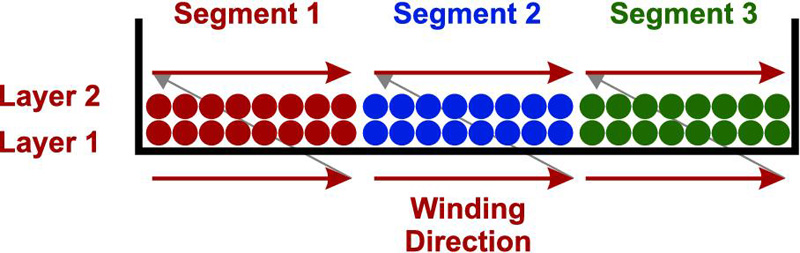
Figure 6 shows how the primary of a low-power flyback transformer can benefit from these same techniques. Even in a small bobbin, it is possible to arrange windings in segments. In this example, about 22 turns are wound 1/3 of the way across the bobbin. We then have the choice of winding back on top of these windings, or using a turn to take the winding back to the beginning before adding another layer. This is knows as a z-wound segment, and it is used to minimize capacitance.
Click image to enlarge
Figure 6: Flyback Transformer Two-Layer Primary Z-Wound in Three Segments.
This technique is repeated for three segments of the winding as shown in Figure 6. You can use this winding technique even if you are building a transformer by hand for prototypes. It is worth experimenting with this since the results are quite remarkable.
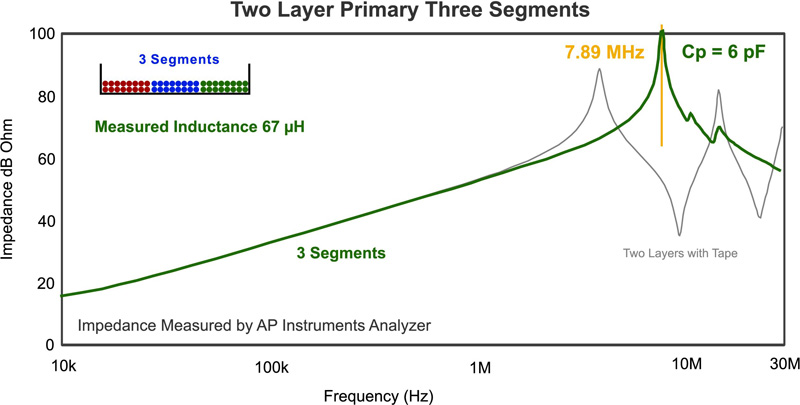
Figure 7 shows impedance measurement of the segment-wound primary. The first resonant peak is now pushed out to 7.9 MHz, corresponding to an impressively low 6 pF of primary capacitance. This is more than a ten times reduction in primary capacitance, and it is achieved with no materials cost.
Click image to enlarge
Figure 7: Primary Impedance Measurement with Two Layers of Primary Z-Wound in Three Segments.
You can also see form Figure 7 that there are no sharp resonant dips in the impedance. This has a direct impact on the circuit waveforms, as shown in Figure 8. The initial turn-on spike is reduced several times, and the current ringing is completely eliminated.
Clcik image to enlarge
Figure 8: Primary Switch Current with Minimum Capacitance Winding Layout. Notice the Greatly-Reduced Initial Spike and Complete Elimination of Ringing. Capacitance is Reduced to 6 pF.
The reduced turn-on spike greatly reduces the peak stress on the power FET, and reduces EMI. Without the following current ringing, it is much easier to tightly control the peak current without false tripping, and the converter can be much more ruggedly controlled.
Summary
Attention to the details of transformer windings can greatly improve the performance of your switching power supply. Simple changes to the high turns-count windings can greatly reduce winding self-capacitance. The improved winding techniques need not add significant cost to the design.
Even if you are working on low-power flyback converters, pay close attention to how the magnetics are wound, and do not be afraid to instruct your manufacturer to make changes to improve performance. You should also be willing to develop your own prototypes in the lab to test these concepts for your power supply.
Additional Reading
[1] Techniques for measuring transformer impedances, www.ridleyengineering.com.
[2] Magnetics Design articles at Ridley Engineering Design Center www.ridleyengineering.com
[3] Learn these techniques and more at the Hands-On Ridley Engineering 4-day Workshops. www.ridleyengineering.com