Force Sensing Provides Flexibility and Reliability
Force sensing is understood as an input or control function that requires a force or pressure – however strong – to trigger a function.
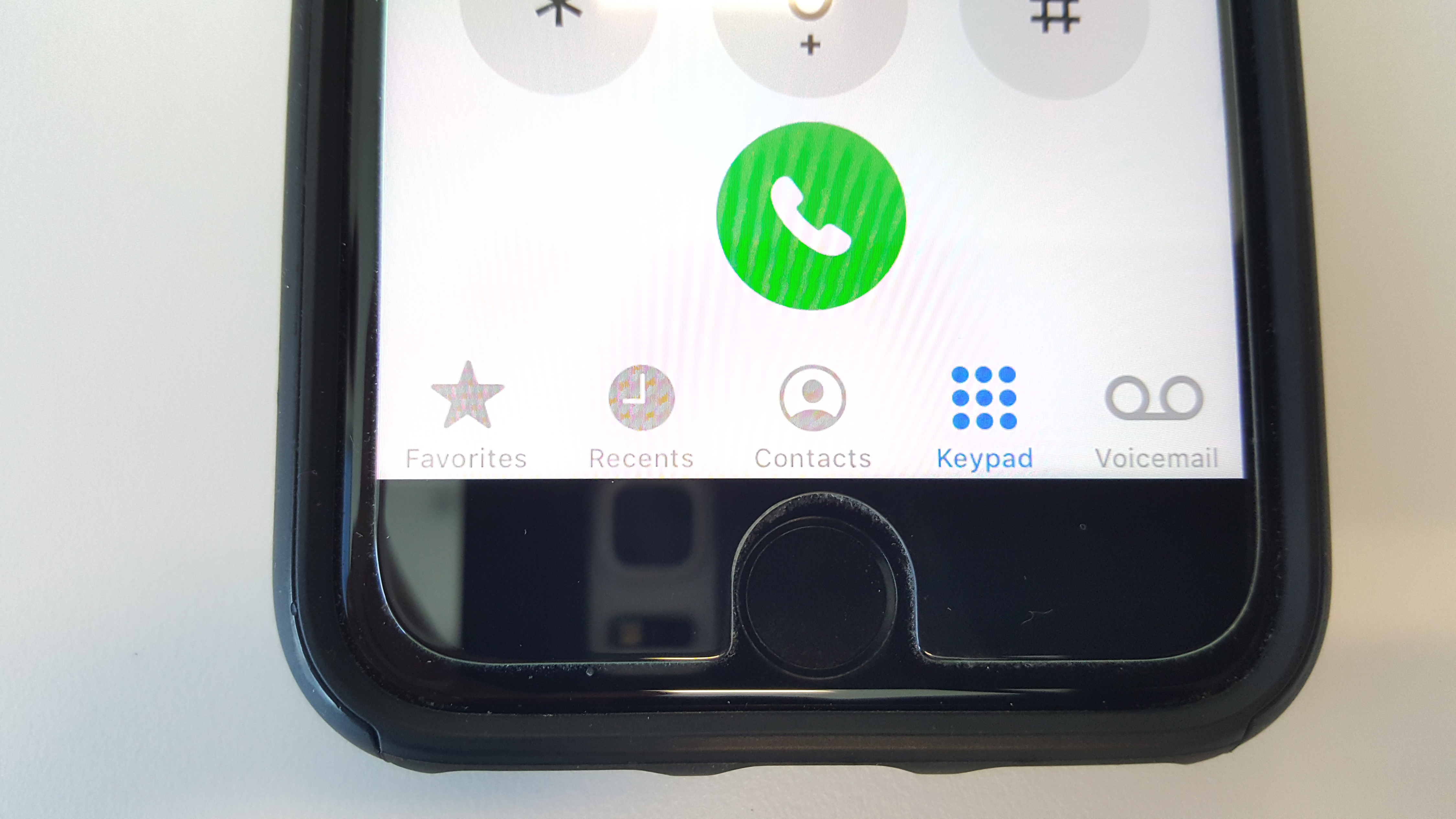
Figure 1. Early generation smartphones featured a force-sensing home button
Force sensing can be employed so that a false positive can be avoided, as well as expanding on input possibilities, such as coupling this with menu selections. The most common use of force sensing can be found on previous generations of smartphones that required touch to wake-up and perform other functions. Smartphone manufacturers used a static, demarcated area that was pressure-sensitive. Instead of a button that mechanically moves, the home button provided haptic feedback to give users the feel of pushing a button. Even earlier generations of smartphones had home buttons that did deflect upon touch.
Preventing False Triggers in Automotive Applications
Many concept cars at CES this year had touch screens that nearly replaced the entire dash. The cluster, climate, and infotainment controls were all replaced by one giant capacitive touch screen. Designers are aware that many current center console touch screens are simply too small. Drivers are required to scroll through several layers of screens to perform what once could be done by a simple push of a button. In addition, by requiring the driver to take their eyes off the road for a significant amount of time, the small screens also pose a safety hazard. The screens had to get bigger. A capacitive touch screen is susceptible to false triggers — situations when the user comes close to the screen with their finger or accidentally brushes the screen. If the entire dash is a capacitive screen, there will be too many false triggers that wake up the screen and potentially change settings. Designers needed to establish certain areas of the screen that would function more like a home or “on” button. But the location of these would vary from model to model and could not be demarcated like the smartphone.

Click image to enlarge
Figure 2. Giant capacitive touch screens featured on newer cars are susceptible to false triggers which can be prevented using a force-sensing home button
Employing a force sensing solution would allow for the reduction of false positives. Automotive designers could create areas where a force was required to turn on portions of the screen. If there is no defined pressure, no function is triggered. Consequently, just touching the device would not trigger a function by mistake. This is especially important at night when errant touches will result in relatively bright, distracting screens. Only a defined pressure or force that causes a minimum deformation of the control surface results in the execution of the desired control action. Just how strong the force applied needs to be or how far the control surface should deform is dependent on the material used and the trigger points that are defined by the system.
Advantages of Digital Proximity Sensors
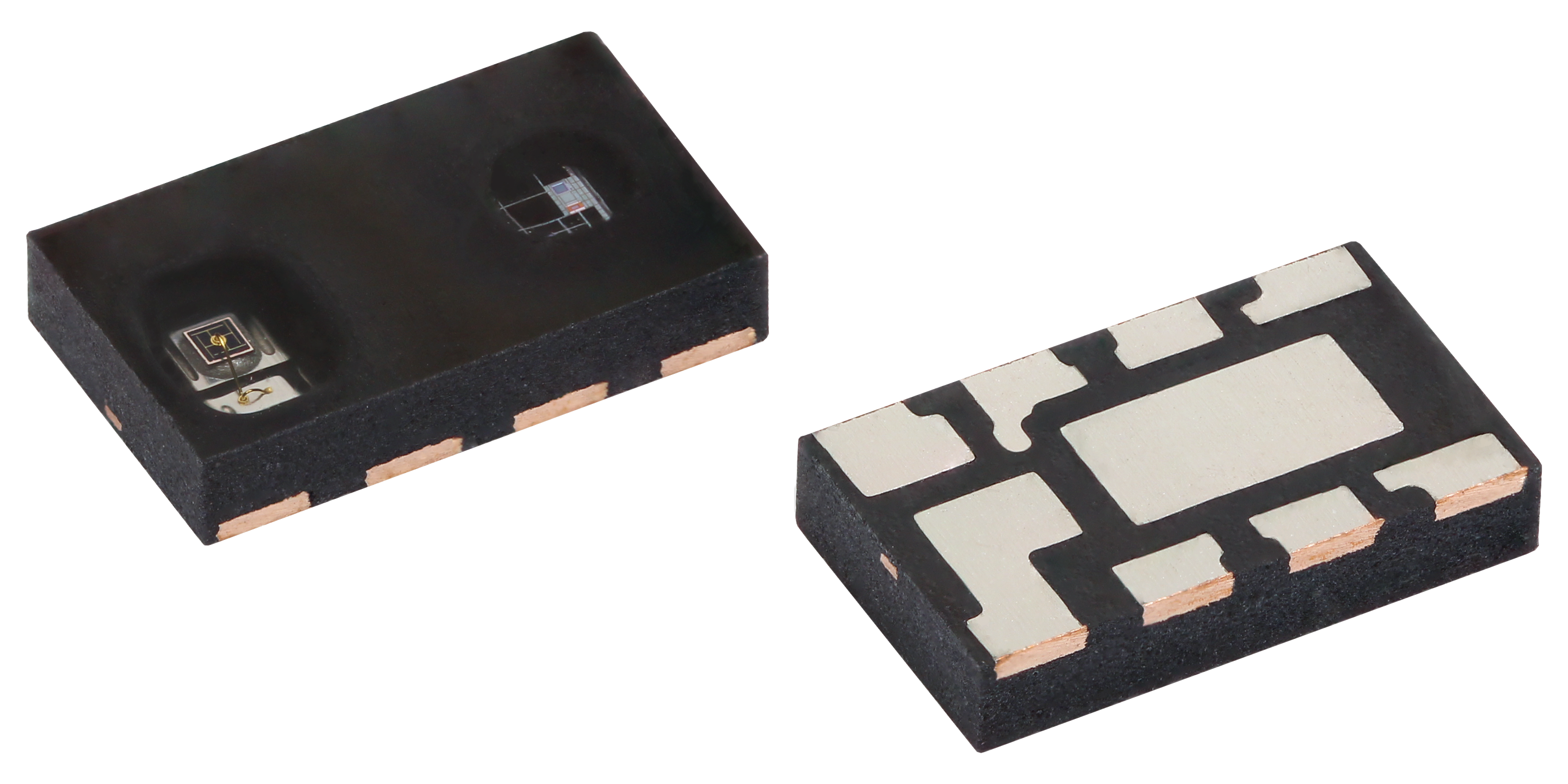
There are several ways to create a pressure or force-sensing solution. While a pressure sensor could be used, it would be relatively expensive, require a lot of PCB real estate, and will not be reliable enough to prevent malfunctions or missed operations. An optical solution using discrete infrared emitters and a phototransistor or photodiode is also possible, but may fail because of the very high tolerances and low resolutions that these parts offer. This leaves us with an optical solution that is based on a digital proximity sensor.
Click image to enlarge
Figure 3. VCNL3030X01 proximity sensor can be used to sense minute deflections in the screen
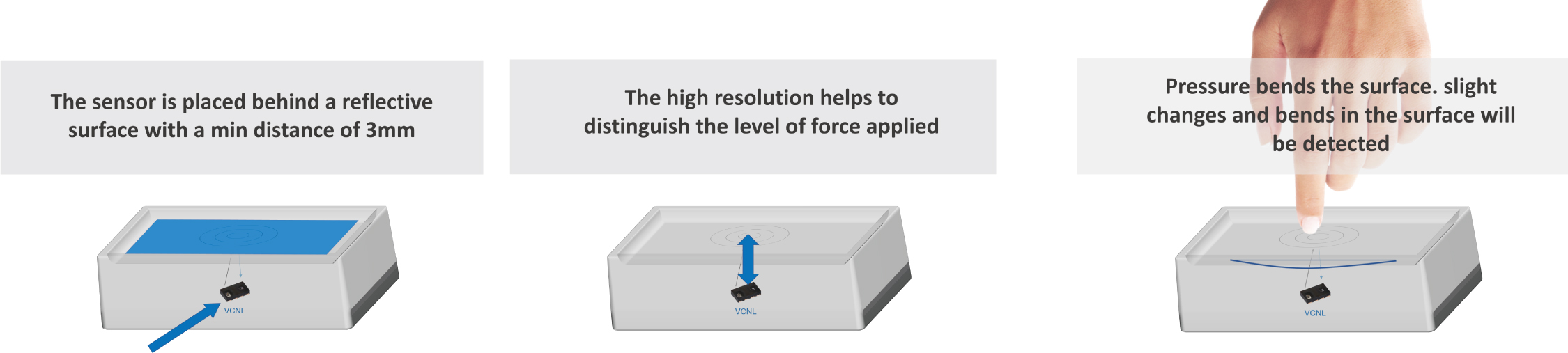
Vishay’s digital proximity sensors can provide a cost-effective force-sensing solution. A proximity sensor, like the AEC-Q101 qualified VCNL3030X01, combines an infrared emitter, photodiode, and signal processing IC in a single package. In the force sensing application, infrared light is emitted on to the back surface of the capacitive touch screen, the light reflects to the sensor, and the sensor receives and processes the signal. The output is a digital count, 0 to 65536 for a 16-bit resolution sensor. An increase in the amount of light reflected from the surface would correspond to the screen getting closer to the sensor, which would result in an increased output count. A driver or passenger pressing on the screen in “home button” areas will deflect the screen by 50 μm to 100 μm. If there is a highly reflective material on the inside of the screen in these areas with a proximity sensor pointed at them, force-sensing areas have been created.
HOW FORCE SENSING CAN USE HIGH SENSITRSIVITY PROXIMITY SENSORS
Click image to enlarge
Figure 4. How force sensing can use high sensitivity proximity sensors.
Using an I2C interface, there are several programmable features of Vishay’s digital proximity sensors that make them ideal for this application. The emitter current is programmable. Initial design work can establish the optimal emitter current for the screen location. If calibration is required during the manufacturing process, the emitter current can be easily adjusted from 5 mA to 20 mA in 2.5 mA steps. In proximity applications the emitter is pulsed, and Vishay’s sensors offer four different duty cycles that can be programmed from 1:40 to 1:160 on / off cycles. The sensors feature 16-bit resolution, which is needed to be able to measure the small deflections in the capacitive touch screen. They have a sunlight cancelling feature, allowing the sensor to function in most any ambient lighting environment. Finally, the sensors allow programmable thresholds that trigger an interrupt signal when exceeded. This eliminates the need for the microcontroller to be constantly polling the sensor.
APPLICATION EXAMPLES

Click image to enlarge
Figure 5. Application examples.
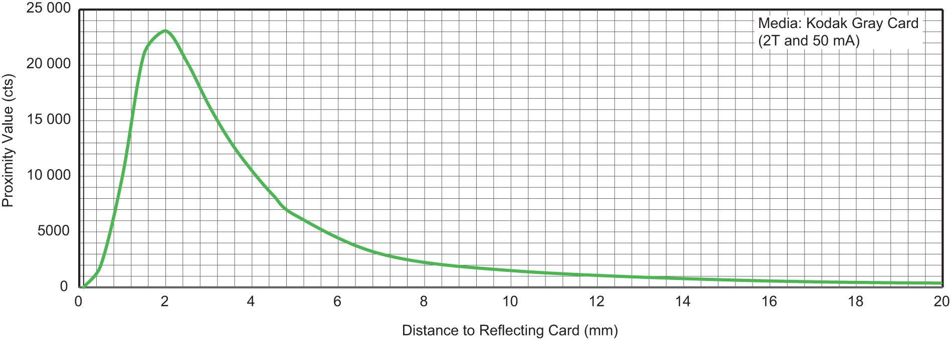
A typical distance curve of the proximity sensor is shown at right.The y-axis is the output count of the digital sensor. The reflective media in this case is a Kodak Gray Card, which is only 18 % reflective. The forward current of the emitter is set at 50 mA. The peak counts occur between 1 mm and 4 mm. There is also a pronounced (greater than quadratic) dip in the counts value to the right of the peak. To achieve the highest possible resolution with reliable results, the detection range should be selected to be close to the peak value, leaving some tolerance for the mechanical stack up. In this case, this is approximately 2 mm between the sensor and the highly reflective input surface that is to be detected.
Click image to enlarge
Figure 6. Output count of VCNL3030X01 versus distance to the 18% reflective Kodak Gray Card where peak resolution occurs at approximately 2 mm
For the VCNL3030X01, a resolution of 50 µm can be achieved with about 2 mm to 3 mm between the sensor and a highly reflective object. This then provides at least 200 to 400 digital counts as the output value for each 50 mm step. This is more than enough for reliable detection and accounts for environmental effects such as temperature fluctuations, material changes, and aging.