Field-programmable gate arrays (FPGAs) trace their origins back to the 1980s, evolving from programmable logic devices (PLDs).
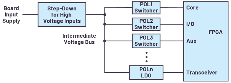
Figure 1. One possible FPGA power tree: a high voltage input supply (for example, 12 V, 24 V, or 48 V) is stepped down to an intermediate voltage bus feeding the POL regulators that power the FPGA
Since the 1980s, FPGA resources, speed, and efficiency have improved rapidly, making FPGAs the go-to solution for a wide variety of computing and processing applications, especially when production volume doesn’t justify application-specific integrated circuit (ASIC) development costs. FPGAs have advanced to such an extent that they’ve also found homes in large-scale deployments. For instance, after successfully speeding up the Bing search engine with FPGAs in a 2013 pilot program, Microsoft expanded FPGA-equipped server usage to its cloud data centers.
FPGA Power System Requirements
FPGAs require a few different low voltage supply rails, each with its own voltage and current specification, to power their internal core logic, I/O circuits,auxiliary logic, transceivers, and memory. These rails may need to turn on and turn off in a specific sequence to avoid damaging the FPGA. Point-of-load (POL) regulators stepdown the board’s higher input supply voltage to the multiple lower rail voltages required by the FPGA. Switching regulators are used as POL regulators when power conversion efficiency is paramount, whereas linear regulators—for example, low dropout (LDO) regulators—are employed for noise-sensitive circuits such as PLLs and transceivers.
Typical board input voltages are 5 V, 12 V, 24 V, and 48 V, while FPGA rail voltages range from below 1V to around 3V. For high input voltages (12V, 24V, 48V), an extra step-down may be needed to generate an intermediate voltage bus that feeds the POL regulators (see Figure 1). Among the FPGA rails, the core supply requires the lowest voltage (around or below 1 V) and highest accuracy (±3% or better), with current levels in the tens of amperes depending on FPGA resource utilization. To prevent logic errors, the supply variation needs to be limited to tens of millivolts, as dictated by the FPGA rail tolerance specification, not just under dc conditions but also during FPGA current transients. The worse the power supply’s dc accuracy, the more bypass capacitance is needed to maintain an acceptable supply voltage under transient conditions. For example, assume a ±3% core voltage tolerance specification. Using a ±1% accurate dc supply leaves a good ±2% allowance for transients. On the other hand, a less accurate ±2% dc supply leaves less room (±1%) for transients, requiring more bypass capacitance than the previous case.
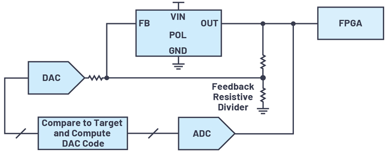
Tweaking or trimming of the FPGA supply voltage level around the default setpoint is required for last-minute design changes, design reuse in another application, board margin testing, and dynamically optimizing system power consumption during development or field operation. Soldering in different resistors in the supply’s feedback network isn’t the quickest or most feasible solution for such situations. One method to achieve voltage trimming is with a digital-to-analog converter (DAC) driving the feedback network of a voltage regulator (see Figure 2). Software code needs to be written for the trim routine to obtain supply voltage measurement data from an analog-to-digital converter (ADC), to compute the correct DAC code, and then slowly adjust the DAC output to the computed code for smoothly ramping the supply voltage, without glitches or overshoots, to the target level. This trim routine needs to be repeated over time to ensure that the supply doesn’t walk away from the target voltage due to components drifting with time or temperature.
Click image to enlarge
Figure 2. POL supply output voltage trimming to target voltage with DAC and ADC
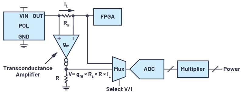
Monitoring FPGA supply voltages, currents, and faults is essential to understanding system health and power consumption under different scenarios because the FPGA is the brain of the electronic system. Such an understanding, coupled with trimming capability, avoids designing supplies for the worst case, saving cost and power. Moreover, an upcoming system malfunction could show up as an abnormal trend in FPGA power consumption, alerting the host controller or service staff before the board or system goes down. Voltage monitoring requires ADCs, whereas current monitoring also requires level-shift circuits to translate the high-side current sense voltage to a ground-referenced voltage; for example, with a transconductance amplifier, as shown in Figure 3.
Click image to enlarge
Figure 3. One possible discrete circuit for monitoring POL supply output voltage, current, and power
One’s head may be spinning after reading this long laundry list of requirements although we have not discussed fault management. What should happen when a POL output goes undervoltage or overvoltage—that is, outside the valid voltage window? Should only the faulting supply be turned off, or should other supplies be turned off too? How does one debug a fault that has shut down theboard?
As one can see, managing an FPGA’s power system can become complicatedvery quickly, distracting from the essential FPGA application. Remember that the FPGA’s power tree is just a portion of the overall power system on a digital processing board. Most of the above requirements also apply to other digital devices such as ASICs, DSPs, GPUs, SoCs, and microprocessors. What is needed is a power system management solution that is simple, scalable, and flexible.
Digital Power System Management
Digital power system management (DPSM) devices deal with the complex power systems found on digital processingboards. They are available with and without integrated dc-to-dc conversion to either replace POL regulators or work with existing POL regulators. Power system managers—that is, without dc-to-dc conversion—add digital monitoring and control to any existing analog power system, whether made up of switchers or LDO regulators. For example, a single device such as the LTC2980 from Analog Devices trims, margins, monitors, sequences, supervises, fault logs, and fault manages 16 POL regulators. Differing channel-count devices (2, 4, 8, or 16 channels) can be mixed and matched to manage hundreds of rails. Similarly, the 2-channel LTC2972 provides a simple introductory solution for monitoring and controlling the two most critical rails in such a power system; for example, the FPGA core and auxiliary rails.
2-Channel Power System Manager
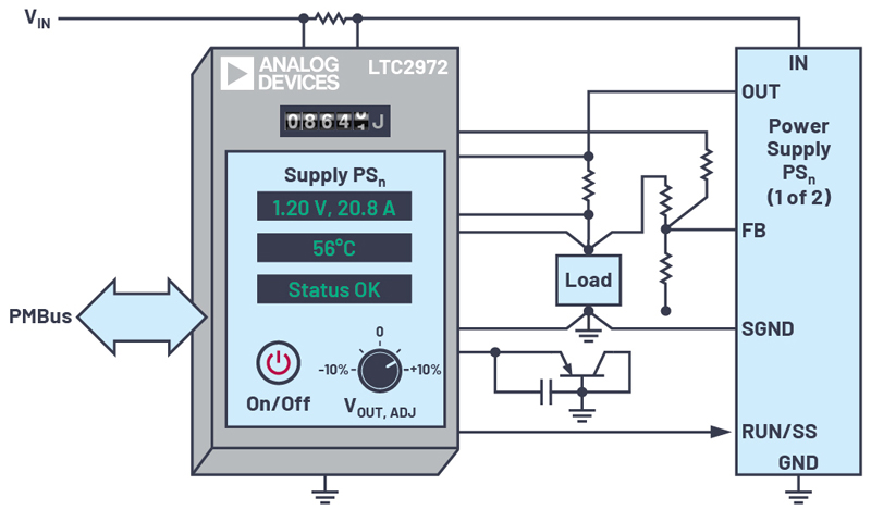
A2-channel power system manager adds comprehensive software-based monitoring, control, and black box fault recording to the power systems of FPGA, ASIC, and processor boards, accelerating time to market, enhancing system reliability, and optimizing board energy consumption (Figure 4). In a device like the LTC2972, POL supply output voltages are trimmed, margined, and monitored using a best-in-class 16-bit ADC with 0.25% total unadjusted error (TUE), improving board yields and long-term performance. The ability to tighten POL output voltage to ±0.25% accuracy leaves plenty of room for it to move during load transients (±2.75% for a ±3% FPGA rail specification), significantly reducing needed bypass capacitance and freeing up board space. Supply output currents are measured using a sense resistor, inductor DCR, or the IMON output of a power supply. The voltage and current measurements are multiplied internally to provide a convenient POL power output reading.
Click image to enlarge
Figure 4. A 2-channel power system manager like the LTC2972 provides intermediate bus energy monitoring and POL output power monitoring
Supply sequencing, supervision, and EEPROM fault-logging are built into the LTC2972. Sequencing is accomplished with time delays written to an internal register or with cascaded power-good signals. Dedicated fast comparators signal faults when POL input voltage, output voltage, and temperature stray outside digitally settable low and high thresholds. Faults trigger EEPROM black box recording, simplifying failure analysis while providing insight into future system improvements. A first fault command provides additional insight into causes of system failure. Faults can be flexibly propagated to other supplies or other DPSM devices.
A power system manager features voltage, current, power, and energy monitoring of the intermediate bus input to POL converters. Monitoring circuit board power and energy use is a prerequisite for managing, optimizing, and reducing their consumption in order to lower server and data center cooling and utility costs. The power system manager relieves the host of burdensome polling and computation by conveniently providing the input energy, reported in joules, and the elapsed time through a PMBus interface, the industry standard for communicating with power management and conversion devices. When combined with its digital measurements of POL output voltages, currents, and power, the use of a power system manager enables long-term monitoring of a power system’s conversion efficiency.
Programmable power-good, or general-purpose input/output (GPIO), pins are available with each channel. Multiple power system managers can be connected together to coordinate sequencing and fault management of more than two rails. PMBus-compatible commands over an I2C/SMBus interface are used for flexible programming and data readback of the power system. Configuration is managed through the development environment, such as LTpowerPlay which supports all of Analog Devices’ DPSM products (see Figure 5). Once the internal EEPROM is programmed with the needed application-specific configuration, no further software coding is required for autonomous operation.
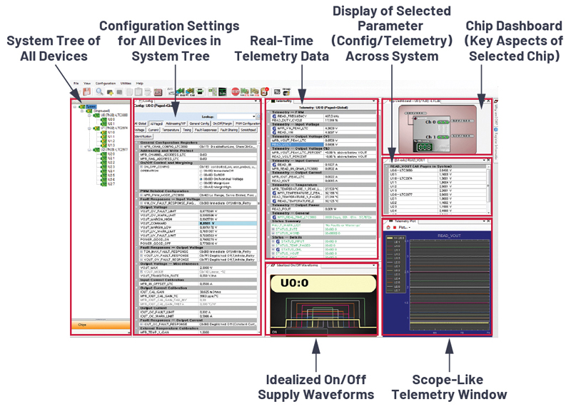
Click image to enlarge
Figure 5. Development environments like LTpowerPlay for DPSM devices eliminate the need to code for autonomous operation.
FPGAs are spreading to all kinds of electronic systems, even taking over the job of ASICs, but they come surrounded by a complicated power system. Digital System Power Management devices can help manage this complexity.