From Cold Crank to Load Dump: A Primer on Automotive Transients
Advances in automotive technology have dramatically increased the number of sophisticated electronic circuits required to improve driving experience and safety in a typical automotive system
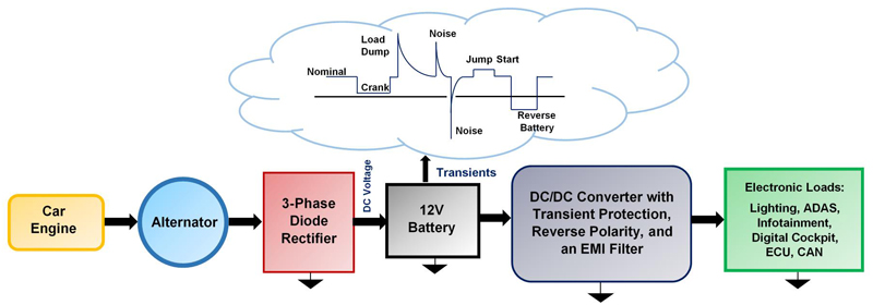
Figure 1: Typical Automotive Electrical System
New vehicles provide infotainment systems with high-resolution displays, an enhanced user interface, and numerous connectivity options. Improved safety features include LiDAR for collision avoidance, as well as multiple cameras and sensors for driver awareness. Many of these electronic modules are connected to 12V or 24V battery systems, which means they are subject to harsh and dynamic transient environments. These conditions challenge power supply designers to ensure reliable circuit operation in extreme environments.
Figure 1 shows a typical automotive electrical system for a car. Typical loads for the automotive battery system include the infotainment system, ADAS, digital cockpit, lighting, electronics modules (ECUs), and CAN bus.
The transients on a traditional automotive power supply range from severe, high-energy transients generated by the alternator to low-level noise generated by the ignition system. This article introduces common automotive transient conditions (e.g. reverse battery, cold crank, warm crank, and load dump), and discusses the causes of these transients in addition to system design challenges.
Cold Crank
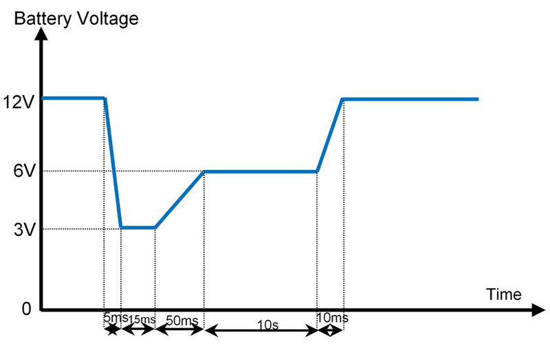
During cold weather conditions, both the car battery and engine can be subjected to extremely cold temperatures. A cold crank pulse occurs when the battery voltage drops after the starter draws a high current to turn on a cold engine. Under cold-crank conditions, the battery voltage can drop below 3V (the worst-case condition) for 15ms to 50ms.
After this period, the battery voltage ramps up to about 6V, where it remains for few seconds before returning to the nominal voltage within a rising time of few milliseconds. Figure 2 shows the battery voltage profile under typical cold-crank conditions at low temperatures. ISO 7637-2, Test Pulse 4 provides details for this type of starting profile.
Click image to enlarge
Figure 2: Typical Cold-Crank Pulse
Under typical conditions, the battery starting profiles are very similar for different automotive manufacturers. With respect to the voltage levels and timing, there are variations among different original equipment manufacturers (OEMs).
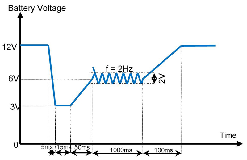
Depending on the OEM specification, a low-frequency sinusoid may also be included in the starter profile pulse. The sinusoid (e.g. 2Hz) represents the alternator noise during crank. The ISO 16750-2 standard describes several starting profiles using an injected sinusoid, and may be referenced by the OEM specification. This waveform is often referred to as a severe cold-crank pulse (see Figure 3).
Click image to enlarge
Figure 3: Severe Cold Crank Pulse
Cold Crank System Challenges
During a cold crank starting condition, the power solution should ensure that there is continuous, stable output regulation for inputs as low as 2.8V for a short duration. A converter (eg. a DC/DC buck/boost converter such as the MPQ8875A-AEC1) with a wide VIN range can be used to address low input voltages.
Warm Crank
A warm crank pulse occurs when the battery voltage drops as the starter draws a high current to turn on a warm engine. Although a warm crank pulse is very similar to a cold crank pulse, the voltage drop and shortened pulse duration are typically less severe. ISO 16750-2 and ISO 7637-2, Test Pulse 4 also describe starting profiles for warm cranks.
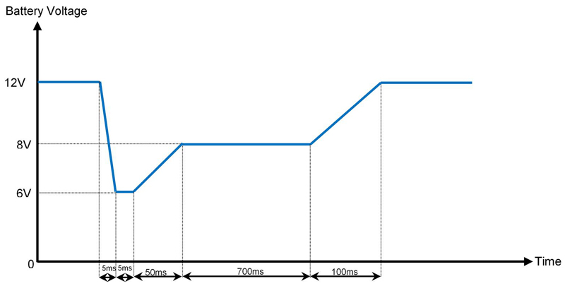
During a warm crank pulse, the battery voltage can drop to 5V or 6V, and the voltage falling time is often shorter than it is for cold cranks. After a short duration of about 5ms, the battery voltage then ramps up to about 8V, where it remains for less than a second before returning to the nominal voltage. Figure 4 shows the battery voltage profile under warm crank conditions.
Click image to enlarge
Figure 4: Typical Warm Crank Pulse
The battery voltage profile for this pulse is very similar for different automotive manufacturers, but there are variations among different OEMs for the voltage levels and timing. An example of a warm crank pulse condition is automotive start-stop, where the engine shuts down at a complete stop when the brake is depressed, then restarts when the brake pedal is released.
Warm Crank System Challenges
Many vehicles require that certain functions continue operating, even during conditions such as warm crank. For example, a car radio should not suddenly stop playing music when the warm engine restarts, and the LCD display panel should not flicker or have a degraded video. It is recommended to use a DC/DC boost or buck-boost converter with a wide VIN range to address these types of low input voltage conditions, such as the MPQ8875A-AEC1.
Reverse Voltage
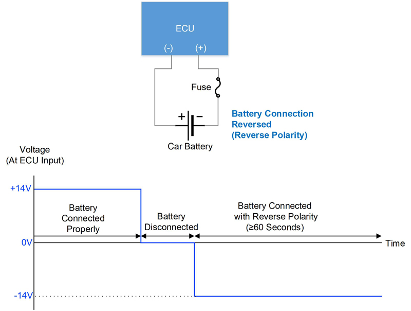
A reverse voltage — or reverse battery — condition occurs when the car battery is disconnected from the system and accidentally reconnected with the battery polarity reversed. This creates a negative voltage across the input supply connector, which can damage the power supply and other circuits. Many ICs are rated for only a few hundred millivolts of negative voltage (e.g. -0.3V), and other components may be sensitive to the polarity. A reverse protection diode or MOSFET is typically used to protect circuits against this condition.
Figure 5 shows a set-up in which an ECU is connected incorrectly to the battery. Initially, the 14V battery is connected correctly, then it is disconnected. When the battery is reconnected to the ECU, the battery polarity is reversed, subjecting the ECU to -14V. ISO and OEM tests define the duration during which the negative voltage is applied, which can be longer than 60 seconds. A fuse is often used to prevent over-current damage, depending on the reverse protection circuit. After a reverse voltage is applied for the specified test duration, it is necessary to reapply the correct polarity voltage to confirm that the module still operates normally.
Click image to enlarge
Figure 5: Reverse Battery Condition
Reverse Voltage System Challenges
It is critical to protect allICs and components from exposure to negative or reverse voltages. Exposure to these conditions can result in severely degraded or damaged components. It is recommended to use devices such as diodes and MOSFETs to provide these protections.
Load Dump
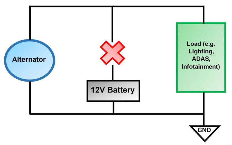
A load dump transient is the voltage surge generated when the battery is disconnected while the alternator is still connected to other electronic loads (see Figure 6). A load dump can occur when the battery is accidentally disconnected while the vehicle is running. Common instances include when the battery terminals are corroded, have a poor connection, or when the battery cable is degraded.
Click image to enlarge
Figure 6: Load Dump Condition
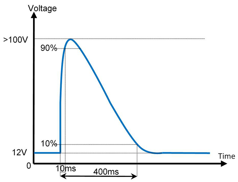
The peak voltage of the surge can exceed 100V, and the surge takes up to 400ms to decay. ISO 16750-2 and ISO 7637-2, Test Pulses 5a and 5b, are typically referenced for specific load dump transient pulses. Each of these standards describe two types of load dump transients.
1. Unsuppressed: The high-voltage load dump transient surge occurs when the battery is disconnected and while the alternator still supplies power to the system, which results in an unclamped waveform (see Figure 7). In this case, the alternator has no internal clamping or means of suppression, so modules and devices connected to the alternator are subjected to this large transient.
Click image to enlarge
Figure 7: Unsuppressed Load Dump Pulse
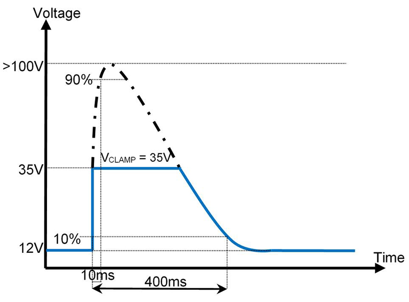
2. Suppressed: When the load dump transient surge occurs, the waveform is suppressed by avalanche diodes in the alternator’s rectifier. This results in a clamped waveform (see Figure 8). In this scenario, the clamping protection in the alternator suppresses the transient to a lower voltage (typically between 32V and 40V) in most 12V systems.
Click image to enlarge
Figure 8: Suppressed Load Dump Pulse
Load Dump System Challenges
Acircuit must survive load dump without damage or degradation. It is recommended to use TVS diodes or other input protections to protect against load dump conditions. For a suppressed load dump, the required clamping protection for a circuit may only need to be rated between 40V and 45V. In this scenario, a wide VIN buck converter — such as the MPQ4316-AEC1 — can be utilized to meet the system requirements. For an unsuppressed load dump, clamping protection must be rated much higher, which may require a larger and more costly solution.
Summary
Table 1 shows a summary of the automotive transients and pulse conditions described in this article, including common industry testing standards. It also highlights the system challenges that must be considered by the system designer.
![]()
Click image to enlarge
Table 1: Automotive Input Transients, Common Standards, and System Challenges
Conclusion
A typical automotive module must address most or all of the transient conditions discussed in this article. A basic understanding of these critical automotive transients is necessary to allow an automotive system engineer to design a robust solution.
While designing a reliable power circuit for extreme conditions can be challenging, robust automotive components such as the MPQ4316-AEC1 (a buck converter with a wide VIN), MPQ8875A-AEC1 (a buck-boost converter with a wide VIN), and MPQ7200-AEC1 (an LED driver with a wide VIN) offer excellent performance and safety with their ability to handle dynamic environments.


.jpg)
