Multicopter design gets serious for important applications
Initially regarded as toys, multicopters are now serious business. From simple surveying to future delivery solutions, entire businesses are emerging around the design, supply and use of multicopters. With increased adoption comes increased regulation and the multicopter itself needs to be capable of being piloted in a safe and well-controlled manner.
“Drones” and “multicopters” are often used interchangeably, but there are definite differences. Drones can trace their origin back to fixed-wing military applications as unmanned aerial vehicles (UAVs) originally conceived as a low-cost, low-risk surveillance solution. “Multicopter” literally means “many wings” and usually refers to an airborne rotorcraft with more than one rotor.
While traditional aircraft designers devote a lot of effort to solving aerodynamic and mechanical challenges, the rapid development of MEMS-based microelectronics has focused multicopter design efforts on the electronics portion. Model based electronic control allows the reduction of aerodynamic instability, which leads to increased flight performance and maneuverability.
Multicopters have brought new possibilities to unmanned aerial vehicles. Seen from a commercial perspective, the most prevalent civil application is the flying camera, which often includes ‘follow me’ functionality and autonomous navigation.
Initial development
Much of the early input to multicopter development came from academic circles, including various open-source communities and universities demonstrating examples of control engineering. The “wild ones” started with FPV (first person view) races. Within only a few years, the FPV races developed from a “game in the backyard” to the “Drone-prix” in Dubai with $1M prize money.
As fast as the technology is growing, so is the surrounding legislation. Many countries - including the US, Germany and the UK - are drafting guidelines and rapidly developing legislation to limit where and how multicopters may be flown as well as defining unacceptable uses and licensing requirements for pilots – especially anyone planning to use a multicopter to deliver a commercial service.
The legislation also, to an extent, drives the technology. It is not acceptable to have multicopters falling out of the sky or colliding with other objects – buildings, power cables or, worst of all, commercial flights. There are many important areas in multicopter technology but the advent of this legislation puts power management / motor control and vision / sensing at the forefront of ensuring that multicopters are capable of safe sustained and controlled flight.
Rapid system solutions
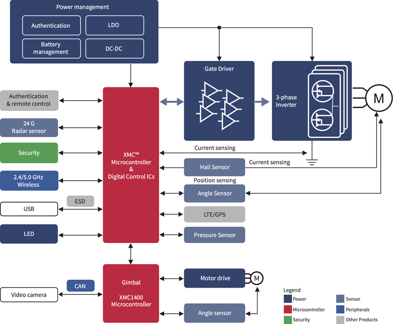
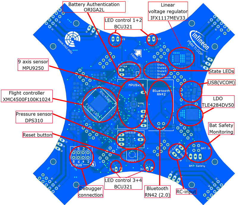
Figure 1 illustrates the main electronic sub-systems for a professional multicopter. As the diagram shows, these devices are sophisticated systems in their own right. The major differentiator between ‘toy drones’ and professional multicopters is that, in ‘hobbyist’ applications, to be able to fly and provide fun is enough. In professional applications, multicopters have to provide a useful function as well. Most often this is a vision system that requires video processing, gimbal control and other functionality to be integrated into the control system.
Click image to enlarge
Figure 1: Overview of the main electronic sub-systems of a typical multicopter
Coupled with the highly accelerated design cycles of this rapidly growing sector, the need to design the ultimate sophistication at the lowest possible size, weight and power consumption brings huge challenges to multicopter design engineers. One of the simplest, fastest and lowest risk ways to implement a multicopter using the benefits of FOC is to begin building from the base of a good reference system. One such system is the comprehensive Infineon XMC4500 iMOTION–based multicopter demo board.
At the heart of the system is the flight controller, which is built around an Infineon XMC4500 ARM Cortex-M4 32-bit microcontroller. IR2301 drivers, low-voltage MOSFETs and MPU9250 Invensense inertial measurement unit (IMU) provide the additional units that make up the electronic powertrain, motor control and flight sensing functional blocks.
Either 6- or 9-axis modes can be implemented using the demo board, and the standard interfaces and connectors of the IMU give designers the flexibility to work with systems they are already familiar with. Utilizing the XMC4500 demo board and the DAVETM platform for microcontroller programming, project development time and cost can be reduced by as much as 30%. Furthermore, flight times are assured by the onboard ORIGATM authentication hardware.
Altitude sensing is provided by the highly accurate, high-resolution, DPS310 pressure sensor, while a 24GHz radar system can be incorporated to measure both the presence and proximity of objects and their velocities. An interface for a GPS breakout board offers the option for more sophisticated route mapping. Finally, an XMC1400 microcontroller forms the basis of a closed loop control system for a gimbal camera along with onboard angle sensors and motor drivers, allowing easy development of professional-grade aerial surveillance systems.
Motor control and power management
The ability to control speed accurately and to manage the relative speed of each motor in a four, six (or more) motor design is important to change yaw, pitch and roll and thus control height, direction and speed. On the one hand, there is only little redundancy on the “low motor count” multicopters, even if there are already emergency landing modes for vehicles with two rotors. On the other hand, the overall flight performance is determined by the dynamics of motor control at highest possible efficiency.
Permanent Magnet Synchronous Motors (PMSM) can be controlled in three configurations: as a BLDC (trapezoidal commutation), sine commutation or as a Field Oriented Control (FOC). FOC is a mathematical vector control technique for controlling AC and brushless DC motors. It was a key milestone when the large multicopter companies started to use FOC solutions. The complexity of sensorless FOC, especially for high-speed motors, is quite high. However, FOC brings benefits in terms of improvements in the efficiency and reduced torque ripple/vibration - crucial for camera operation.
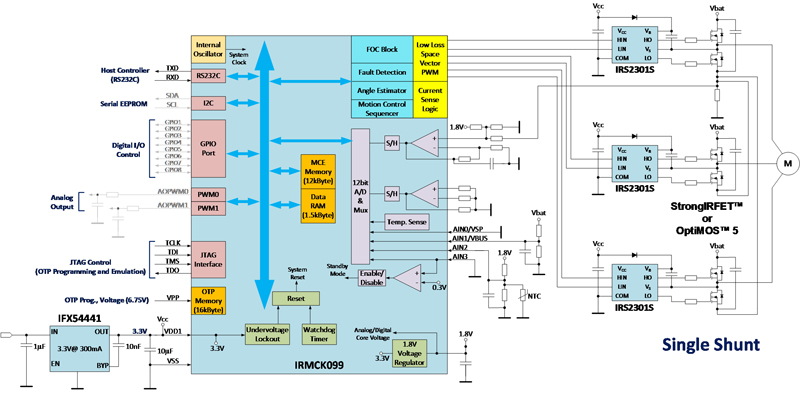
A block diagram of a high efficiency FOC solution used by leading multicopter manufacturers can be found in Figure. 2. The IRMCK099 ASIC integrates the flexible Tiny Motion Control Engine (TinyMCE) for highly dynamic and sensorless control of motor torque over the full speed range by a combination of hardware and Infineon-supplied firmware elements. The simple-to-use iMOTION motor controller allows customers with little motor control experience to take flight rapidly.
Click image to enlarge
Figure 2: High efficiency FOC solution for multicopter drives
Key components of the control algorithms, such as the angle estimator are provided as complete pre-defined control blocks. The ASIC is designed to eliminate external components – thus reducing weight and complexity – by including an A/D converter, analogue amplifiers, an overcurrent comparator, watchdog timer and internal oscillator. Various forms of speed commands can be accommodated via UART, frequency input, Vsp and duty cycle options.
If a higher degree of flexibility is needed, there are microcontroller (XMC1300, XMC4x00) based solutions available as well. Figures 3a and 3b show, respectively, a multicopter evaluation system and the two motor control boards that can easily be exchanged on the system board to demonstrate different motor control concepts. Half-bridges (two power transistors in a package), power stages (power transistors and drivers in a package) or even full integration is possible, depending on voltage, power and budget.
Clcik image to enlarge
Figure 3a. Multicopter System solution for evaluation and educational purposes. The motor control boards are plugged on the arms of the board and can be exchanged easily, thus a fast comparison of the performance of BLDC and FOC solutions is possible
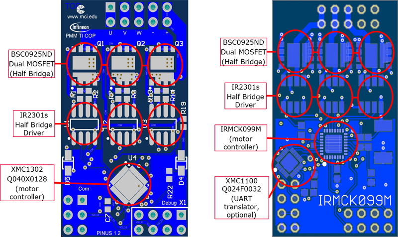
Figure 3b: Motorboards for the evaluation of different motor control concepts on the left side there is a microcontroller based solution (XMC1300), on the right side a FOC solution based on the ASIC (Application Specific Integrated Circuit) IRMCK099M
Sensing and vision
As commercial usage expands, the increasing price of multicopters and flight beyond line-of-sight become huge differentiators from the ‘toy drones’ on the market. The ability to measure altitude and detect objects in – or close to – the flight path is critical for professional multicopters.
Object detection is becoming an increasing feature of daily life. Through radar based systems our cars are able to maintain distance from the vehicle in front. Now, designers are looking to leverage this established and highly qualified technology to provide easy-to-implement systems on sophisticated professional multicopters. While it is not permitted to use 77 GHz based automotive solutions for other applications, there are solutions available with 24 GHz and 60 GHz at Infineon. Although the 24 GHz has a limited spatial resolution it is already used for obstacle avoidance and landing velocity control. First steps towards Radar technology can easily be achieved when using the available demo kits. For high resolution applications, the 60 GHz Radar is the first choice; this technology is also used in smart watch demos for gesture recognition, so there is no limitation for obstacle detection and classification in multicopters.
Similar to all aircraft, sensor fusion and advanced filtering methods play an important role in the realization of a reliable attitude controller, which has to combine all the measurements from various sensor signals from the IMU (Inertial Measurement Unit), DPS310 pressure sensor and other sensors.
Power security is a relatively new concept. Non-approved and/or inferior aftermarket batteries can jeopardize the multicopter, cause damage to property and/or cause injury to the operator or a third party. Professional multicopter designs now demand intelligence in the batteries and power management system to ensure that the multicopter will only fly when approved batteries are fitted. A widely used solution for authentication is the ORIGATM.
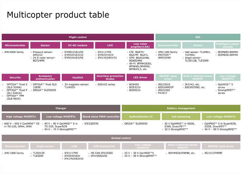
As multicopters move into the professional world, advanced components such as these – supported by the appropriate reference designs and tools - will allow designers to rapidly design, develop and deploy systems that address the ever-more demanding needs of today’s professional users (see Figure 4).
Click image to enlarge
Figure 4: A wide variety of multicopter-oriented products facilitate rapid and integrated designs