Galvanic Isolation Keeps Pace with Control Requirements
Protection against voltage surges and noise is essential in many systems in the automotive, industrial and green-energy spaces.
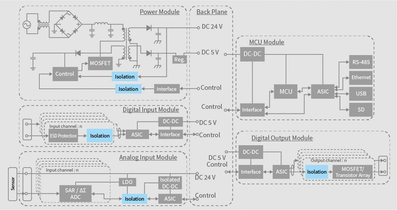
Figure 1: Isolation locations in a PLC
There are two distinct trends in the design of the electronic systems that support motors. On one side are power generation and electrical distribution subsystems that operate at voltages that are moving toward the kilovolt regime. On the other are high-speed MCUs that enable advanced algorithms to optimise systems performance and operate at voltages close to just 1V.
In a variety of systems, across the automotive, industrial and green-energy domains, designers are looking to use wide-bandgap transistor technologies to take advantage of their ability to support operation not just at higher frequencies but higher voltages. High-frequency operation improves the density of circuits but has proven difficult to achieve with traditional bulk-silicon process technologies because of switching losses. Wide-bandgap devices do not suffer from the same losses.
The wide-bandgap technologies are also more robust and can handle higher supply voltages than many silicon devices. That makes it possible to achieve high power densities at low cost. This enables smaller inverters and, in automotive systems, chargers that can deliver more energy across an array of battery cells to support fast-charging protocols.
Higher-frequency operation means using control algorithms generating pulse-width modulation (PWM) signals that can respond quickly to sensor signals and ensure power-transistor switching operations are synchronised correctly. More sophisticated control algorithms also optimise motor and inverter performance for efficiency.
Low-voltage devices and the support devices around them need to be protected against surges and spikes from the high-voltage. If the different sections of the system are not isolated from each other, electrical noise and spikes can propagate from a high-voltage subsystem to the low-voltage circuitry. The presence of high-voltage and high-current circuitry on the same PCB or within the same system can cause many problems, including transient issues such as data corruption, safety hazards and permanent damage to the circuitry inside these devices.
High-current spikes may cause damage to semiconductor components, potentially resulting in latchup conditions that lead to total system failure. The heat generated in components not designed to handle the stresses can lead to fires. And the breakdown of insulation caused by these spikes may lead to I/O cables carrying dangerous voltage and current levels that result in electrical shocks to operators and users. Even at relatively low levels, exposure to repeated electrical surges can lead to reduced system reliability because of progressive breakdown of the isolation barrier materials.
Electrical noise can also be problematic. Such noise interferes with the inputs to sensitive mixed-signal components such as analogue-to-digital converters, resulting in false readings. Stronger pulses may lead to bits being flipped in transfers from memory and other digital peripherals to the host processor.
The number of locations where protection is needed is growing. As well as requiring internal I/O, often subsystems will communicate with each other across a network to further improve efficiency and be better placed to react to sudden changes in conditions in a coordinated fashion. This points to a growing demand for high-speed communications across cable networks and system backplanes. In the harsh electrical environment of many industrial systems, these connections also need protection against damage from high-voltage spikes and other electromagnetic interference (EMI).
The architecture of a typical programmable logic controller (PLC) provides an example of the many different signals that will need to be protected. In many PLCs, the system functionality is divided among several cooperating modules that are connected by a common backplane. This backplane will usually provide low-voltage power rails that operate at up to 24V alongside 5V control paths to the control modules, plus supplies to a power module.
The power module will generally be split into low- and high-voltage sections. Protection is required for the PWM signal lines that are used to control the switching of power transistors. To avoid shoot-through and similar switching issues, multiple PWM signals may be needed, which increases the number of parallel control signals. Support for reverse-direction signals in the same isolation device enables error and sensor signals to pass from the power stage to the controller.
The PLC will often contain analogue and digital I/O modules for external sensor signals. Protection will be needed across these different signals and be able to support high transmission rates with the minimum board space required. Network modules may need to pass data at rates up to 100Mb/s and need to be protected against high-voltage damage and electrical noise.
The key to much of the protection against surges propagating across voltage domains comes in the form of electrical isolation: a break in electrical paths between the high- and low-voltage domains to prevent the direct transfer of current from one side to the other.
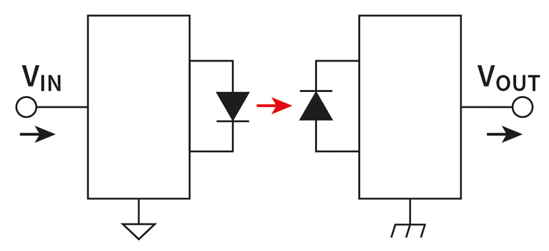
For many years, optical isolation has been used to separate the electrical paths between two subsystems. This works by converting incoming electrical signals into photons using an LED. A non-conductive transparent barrier conveys the light to a photodetector on the receiver side.
Click image to enlarge
Figure 2: Optical isolator
Though optocouplers can be supplied in compact packages, the size of the solution can be a problem where several channels need isolation. Because more than one cannot easily be integrated into a single package without cross-interference between channels, they are generally supplied as discrete. This can cause issues where parallel I/O isolation is needed. Protection for a Serial Peripheral Interconnection (SPI) bus, for example, calls for four individual devices. A second problem for optocouplers is that the maximum datarate they can pass is limited by the response times of both the LED and the photodetector. In practice, the maximum achievable digital bandwidth is around 50Mb/s. Long-term reliability is also an issue.
One technology that provides the option to use integrated devices for parallel I/O is capacitive, though it tends to be suitable for scenarios where a lower level of isolation is required. This form of isolated coupler uses the charge and discharge cycle of a capacitor to transmit data. There is no flow of direct current as this will be blocked by the insulation between the capacitive elements. Though it may be limited by the charge and discharge rates if large capacitances are required, the technology can support high datarates.
Click image to enlarge
Figure 3: Capacitive isolation
Isolation is generally limited to the breakdown voltage of the insulating layers that sit between the capacitive elements. For small devices, this may not be sufficient to block large high-voltage spikes.
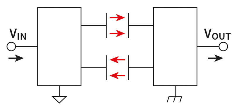
Galvanic isolation operates using the magnetic field generated by the current in the primary winding to induce a current in the secondary winding. When implemented in an isolation solution, one coil acts as a signal transmitter and the other a receiver. This application of magnetic induction for isolation can operate in systems that operate at very high voltages. As a result, the use of magnetic coupling offers a combination of high protection, long operational life and can work at higher speeds than optocouplers.

Click image to enlarge
Figure 4: Magnetic coupling provides the basis for galvanic isolation solutions
Magnetic coupling need not be bulky. Advances in semiconductor technology have made it possible to integrate inductors into small chip-level products. This enables the provision of multiple channels operating in parallel within a single package, delivering further space savings. For example, Toshiba’s DCL54x01 series comprises two co-packaged chips. One is a modulator for an input signal and the other side demodulates the received signal. The use of two isolated dies allows a dual insulation structure, delivering maximum protection. This design prevents shorts between the two sides of the isolation even if the insulation barrier on one side suffers damage. This architecture ensures voltage surges as high as 12.8kV cannot cross to the other side of the barrier and that the components satisfy the demands of the VDE V 0884-11 standard.
Tests based on measurements using standard time-dependent dielectric breakdown (TDDB) tests with 1.2kVrms pulses have shown the structure design provides an expected insulation life of up to 70 years.
Click image to enlarge
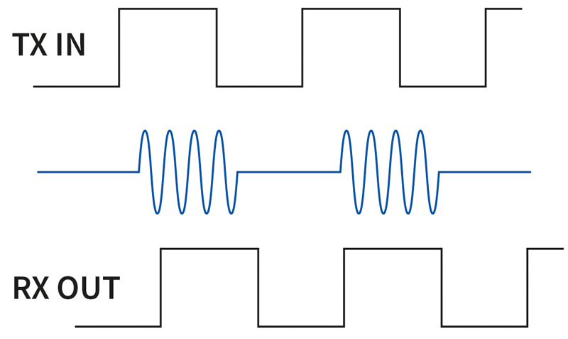
Figure 5: On-off keying
Protection against noise even when operating at high speeds can be provided by the modulation scheme of on-off keying. This form of modulation uses the presence and absence of a carrier signal to signal high and low logic states, respectively. The modulation scheme provides a highly effective and reliable method of communicating PWM signals from a microprocessor to the gate drivers controlling a motor or inverter on the high-voltage side of the PCB. In the case of the DCL54x01, the method delivers a pulse-width distortion of less than 3ns, ensuring accurate transmission of PWM and other high-speed logic-level signals. The method also supports the transmission of data at rates of 150Mb/s or more with high noise immunity, including against common-mode transients.
Common-mode noise is a type of noise where current flows in the same direction on both the signal and ground lines and is often encountered in high-voltage systems. Isolation against it is more difficult to achieve because the shift affects both signal and ground lines and can potentially couple through an isolation barrier, particularly in the case of capacitive isolation products. If the current coupled onto the receiver side reaches a certain level, it may cause a malfunction not just in the isolation interface itself but the system. High common-mode transient immunity (CMTI) is essential for reliable operation. This is readily supported by magnetic isolation products.
Because the isolators can take advantage of the dual-insulation structure to provide protection against high-voltage surges, multichannel operation in small-sized packages is easy to provide.