GaN Devices for Smaller, Lighter, Smoother Motor Drives
Today, the permanent magnet motor, also known as DC brushless motor (BLDC), is widely used and offers higher torque capability per cubic inch and higher dynamics when compared to other motors
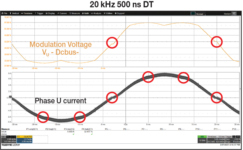
Figure 1: Voltage modulation and phase current at 20 kHz with 500 ns dead time
So far, silicon-based power devices have been dominant in the inverter electronics, but today their performance is nearing their theoretical limits. There is an increasing need for higher power density. Gallium nitride (GaN) transistors and ICs have the best attributes to satisfy these needs.
The superior switching behaviour of GaN helps to remove dead time and increase PWM frequency to obtain unmatched sinusoidal voltage and current waveforms for smoother, silent operation with higher system efficiency. The motor becomes more efficient, when driven by a GaN inverter at higher PWM frequency and with minimum dead time. Power density increases with the substitution of electrolytic capacitors in the input filter with smaller, lower cost, and more reliable ceramic capacitors.
GaN allows the design of motor drives that operate smoother while reducing size and weight. These advantages are critical for the motor drives used in applications such as warehousing and logistical robots, servo drives, e-bikes and e-scooters, collaborative robots and medical robotics, industrial drones, and automotive motors.
Silicon Inverter Limitations
The inverter power dissipation is composed of conduction losses and switching losses. Conduction losses are directly proportional to the RDS(on) of the switches. Reducing the channel resistance helps to reduce conduction losses, but it can increase switching losses. The relation between conduction losses and switching losses depends on the specific technology.
DC and battery-operated motor drive applications have a DC bus voltage that spans from 24 VDC to 96 VDC. With silicon MOSFETs, the PWM frequency is kept below 40 kHz, and the dead time within the range of 200 ns to 500 ns. Low PWM frequency helps to avoid the high switching loss penalty inherent to the Si MOSFET.
Sixth Harmonic Dissipation in the Generated Torque
With silicon devices, the necessary dead time is responsible for the 6th harmonic of the electrical frequency in the generated torque.This harmonic decreases the motor efficiency while increasing the vibrations transmitted to the load and the windings’ temperature.
GaN Advantage
GaN devices have lower switching losses and do not have a body diode pn junction, and thus no associated reverse recovery in hard switching operation. These two factors combined help eliminate the dead time and increase the PWM frequency to a point that the input filter may be substituted with ceramic capacitors. The advantage is quieter operation with a smaller and lighter inverter. The motor runs smoother at a lower temperature and is more efficient. Use of ceramic capacitor reduces cost and increases system reliability.
Body Diode Reverse Recovery
When a MOSFET in a half bridge is turning on against the body diode of its complementary switch, it must deal with the reverse recovery current, that depends on load current and on the turn-on di/dt. So, it is common practice to slow down the turn-on event to reduce di/dt and to reduce the reverse recovery current; however, this requires an increase to the minimum dead time that can be applied to the half bridge.
A GaN FET allows having a repeatable and smooth dv/dt that, in turn, allows a reduction in the dead time.
Dead-Time Elimination Effect
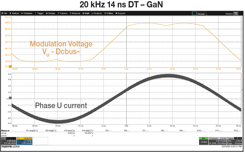
When using discrete eGaN FETs or a GaN ePower stage IC in an inverter, the dead time can be reduced to tens of nanoseconds allowing a smooth voltage waveform to be applied to the motor terminals. Figures 1 and 2 show the difference in modulation voltage and phase current between two different dead-time values. Eliminating the dead time improves the quality (in terms of THD) of the applied sinusoidal voltage that is, in turn, reflected in less distortion in the phase current, less vibrations, and less acoustic noise generated by the motor.
Click image to enlarge
Figure 2: Voltage modulation and phase current at 20 kHz with 14 ns dead time
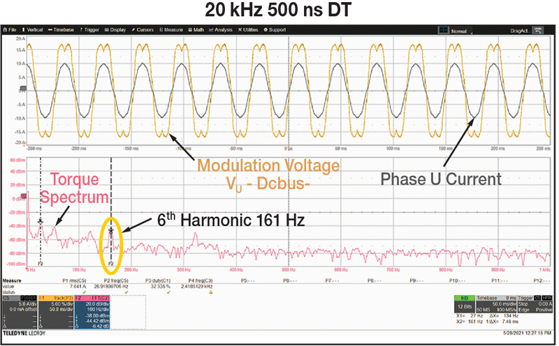
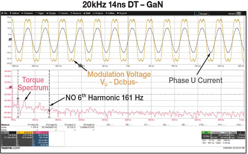
Inserting dead time is responsible for six discontinuities in total for each electrical cycle that appear as a 6th harmonic in the applied torque to the motor. The comparison of the torque signal spectrum is shown in Figures 3 and 4. With the GaN inverter, the applied torque is smoother, and the motor is more efficient because all current gets converted in torque applied to the load.
Click image to enlarge
Figure 3: 500 ns dead time effect on torque signal; electrical frequency is 27 Hz, 6th harmonic is visible. Torque signal is obtained from torque transducer
Click image to enlarge
Figure 4: 14 ns dead-time effect on torque signal; electrical frequency is 27 Hz, torque 6th harmonic is null
PWM Frequency Increase Effect
Reduction of Input Filter
A GaN inverter can easily be operated at 100 kHz PWM frequency. The input voltage ripple is a function of the inverter output peak current, the input capacitance value, and the PWM switching frequency.
If the PWM frequency is increased from 20 to 100 kHz, the input capacitance can be reduced by at least a factor of five to preserve the same input voltage ripple.
The input current ripple is inversely proportional to the PWM frequency. Increasing the PWM frequency has then the double effect of reducing both the input current ripple and the input voltage ripple.
With low PWM frequencies (20 kHz), the required input capacitance is made of polarized capacitors; electrolytic or tantalum. The electrolytic capacitors pose limits on the amount of the RMS current they can support. Tantalum capacitors are expensive.
When the PWM frequency is increased, the minimum required capacitance decreases allowing the use of ceramic capacitors. Ceramic capacitors exhibit lower series impedance in the region between 100 and 200 kHz, are more stable in temperature, and are more reliable. The result is a more compact and reliable inverter, given the same power dissipation and power output.
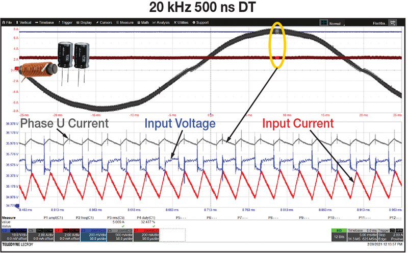
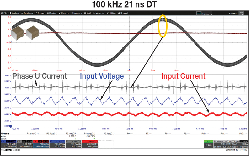
Figures 5 and 6 show the ripple in the input current, the input voltage, and the output current, when comparing two different setups consisting of a conventional and a GaN inverter.
Both setups run an e-bike motor at 36 VDC battery voltage and 5 ARMS phase current. The input voltage and current ripple are similar, so the same conducted EMI is expected. In the GaN 100 kHz solution the output current ripple is reduced and the current in the motor has a better sinusoidal shape.
Click image to enlarge
Figure 5: Conventional inverter with LC input filter at PWM = 20 kHz, DT = 500 ns, L = 6 µH, and C = 2 x 330 µF electrolytic capacitors; Phase U current 500 mA/div, Input voltage 200 mV/div, Input current 200 mA/div, and 50 µs/div zoom timescale
Click image to enlarge
Figure 6. GaN inverter without input filter at PWM = 100 kHz, DT = 21 ns, and C = 2 x 22 µF ceramic; Phase U current 500 mA/div, Input voltage 200 mV/div, Input current 200 mA/div and 10 µs/div zoom timescale
System Efficiency
When comparing the two setups of the Figures 5 and 6 using a power meter system, the GaN inverter running at 100 kHz shows higher total system efficiency than the conventional inverter running at low PWM frequency, and with an input LC filter.
Click image to enlarge
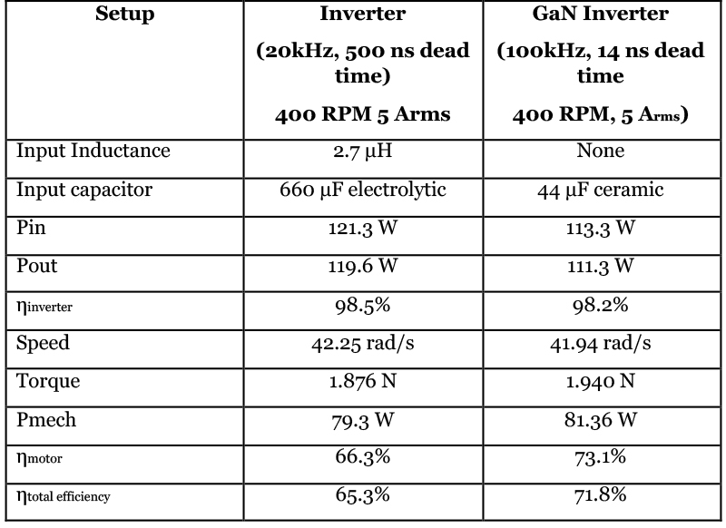
Table 1: Efficiency comparison of Si and GaN inverter-based systems. Torque and speed are measured with a transducer
Table 1 shows that by moving from a silicon-based, 20 kHz inverter to a GaN-based, 100 kHz inverter with almost no dead time, the input filter is reduced in size, weight and cost, and the total system efficiency in the specific operating point is increased by 6.5 percentage points.
Summary
DC and battery powered motor applications are moving from conventional Si MOSFETs and low PWM frequency inverters to GaN-based, high frequency PWM inverters. The advantages are higher system efficiency and the elimination of the electrolytic capacitors and input inductor.


