Hall-effect sensors deliver higher efficiency in brushless-DC motors
Multiple sensor-performance characteristics influence commutation timing and, ultimately, motor efficiency
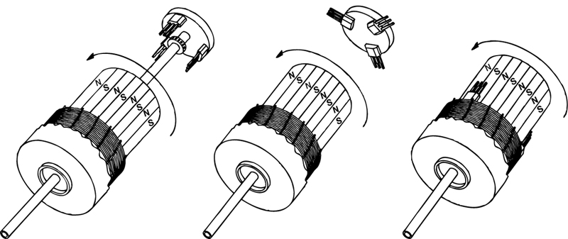
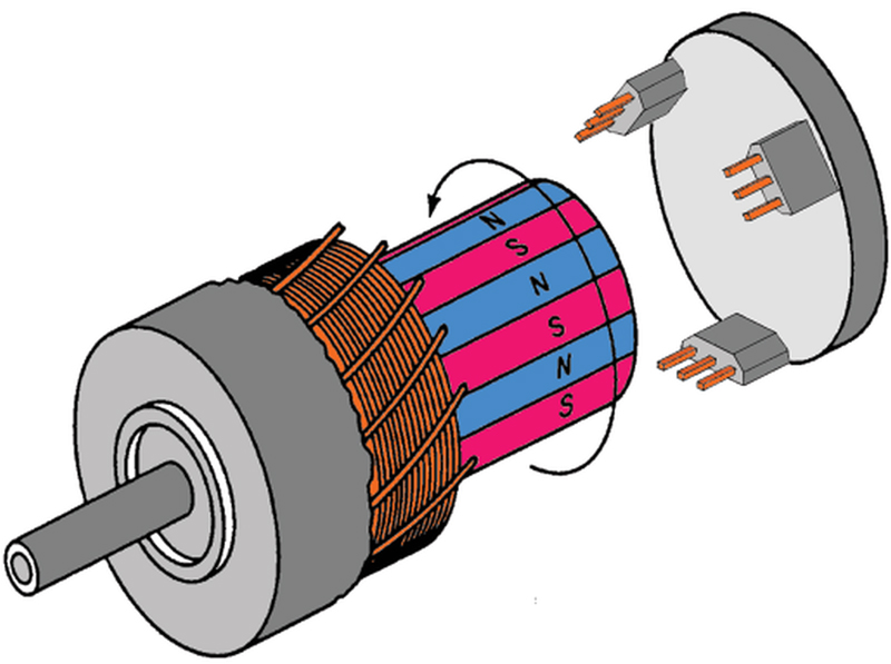
Figure 1: Hall-effect sensors can mount in three locations: inside the motor, at the end of the motor's shaft, and around the rotor shaft's ring magnet.
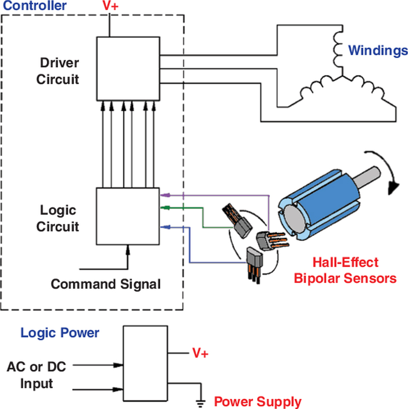
As energy efficiency and cost savings become the biggest drivers in the design of electronic equipment, BLDC (brushless-DC) motor manufacturers must adapt to these new requirements, and deliver motors that operate more efficiently. One way BLDC motor designers can increase efficiency is by selecting the right bipolar latching Hall-effect sensor for electronic commutation. Higher efficiency translates into less material required to deliver the same amount of power in a BLDC motor, which helps reduces cost. Playing a big role in motor efficiency, Hall-effect sensors can significantly affect the reliability, performance, and life cycle of many critical applications, ranging from robotics and portable medical equipment to HVAC fans and machine tools. These applications generally require a highly efficient and quiet motor, which are two key advantages of BLDC motors. Unlike brush DC motors, which use mechanical commutation, BLDC motors employ electronic commutation to control the power distribution to the motor. This entails the use of Hall-effect sensors and control circuitry to detect the position of the rotor. A magnetic field from a permanent magnet or an electromagnet drives these Hall-effect sensors. They respond to a positive magnetic field (south) to operate and a negative magnetic field (north) to release. The Hall-effect sensors can mount in any one of three locations in the motor to measure correctly the motor's position. They may mount inside the motor, at the end of the motor's shaft, and around the rotor shaft's ring magnet (figure 1). Their job is to determine when to apply the current to the motor coils. This data communicates to the electronic controller to rotate the magnet at the right time and orientation. When selecting a bipolar latching Hall-effect sensor to commutate the motor, BLDC-motor manufacturers need to evaluate several key design characteristics to ensure that the motor will operate efficiently. These include sensitivity, repeatability, stability over temperature, and response time. Hall-effect sensors should offer consistent repeatability and stability and provide a fast response to changes in the magnetic field to deliver enhanced motor efficiency. Here's why BLDC-motor manufacturers should evaluate these characteristics when selecting Hall-effect sensors:
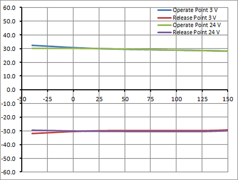
Sensitivity Three factors determine a Hall-effect sensor's sensitivity level: The placement of the sensor with respect to the magnet, the air gap, and the magnet's strength. The sensor is activated by a magnetic field, and changes state—operates and releases—based on magnetic field strength, measured in Gauss. By selecting a high-sensitivity sensor, which is typically rated at less than 60 Gauss, BLDC motor manufacturers can use smaller magnets or less expensive magnetic materials, allowing the BLDC motors to be used in compact designs while reducing costs. This is increasingly becoming an issue as the price for rare earth magnets continues to rise and supply tightens. Another benefit of high sensitivity is that it allows for a wider air gap. This provides greater design flexibility by allowing the motor designer to place the sensor further away from the magnet and still maintain reliability. If the designer does not opt for a wider air gap, the sensor exhibits higher sensitivity, translating into higher reliability and repeatability. The upshot: A Hall-effect sensor with high sensitivity or a lower magnetic switch point delivers more efficient motor performance. As an example, Honeywell Sensing and Control's SS360ST, SS360NT, and SS460S high-sensitivity bipolar latching Hall-effect sensors operate from only 30 Gauss, typical, at 25 °C, and 55 Gauss, maximum, over the full operating temperature range of ?40 to 150 °C. This allows BLDC manufacturers to build smaller products while eliminating the need for higher-cost magnetics (figure 2).
Repeatability High sensitivity allows a Hall-effect sensor to be more repeatable. Repeatability is based on a Hall-effect sensor's latching time. The sensor's output directs current through the coil windings in the motor. This produces a magnetic field that interacts with the field from the permanent magnets on the shaft, causing the shaft to spin. A highly repeatable sensor changes state at the same angular position each time the magnet passes by the sensor. As an example, one complete revolution of the motor shaft is 360 degrees. If the sensor turns on at five degrees when the shaft spins the first time, does it change state at five degrees at the next rotation? A highly repeatable sensor will maintain all of the angular measurements close to the same value, which in this case, is five degrees. This is critical because the timing between the current flow through the coil and the shaft's position must be highly accurate to produce the maximum amount of torque on the shaft. Any delay in a sensor's response to changes in the magnetic field typically leads to lower bandwidth and accuracy errors. An error in the switching point of the Hall-effect sensor reduces the motor's torque, translating into lower motor efficiency (figure 3).
Stability Stability refers to how much the angular position changes over temperature or voltage. A highly stable Hall-effect sensor will require the same Gauss level to turn a part on whether it's at 25 or 125 °C. So if a part operates at 30 Gauss at 25 °C, does it operate around 30 Gauss at 125 °C or does the operating point shift? This is an important characteristic because stability-over-temperature, coupled with high sensitivity, is required for precise position detection. In addition, magnetic stability improves jitter performance—a critical factor in BLDC efficiency, which contributes to less speed variation. Response time Response time is the time it takes for the sensor to change state. As an example, when a 30 Gauss magnetic field level is applied to the sensor, which has an operating point of 30 Gauss, the response time is measured from the point when the Gauss field is applied to when the sensor's output changes state. If a sensor has a slow response time—switching at a different magnetic field level than what is required—it can result in lower bandwidth, accuracy errors, and lower repeatability. Ultimately, this translates into lower motor efficiency and issues commutating a motor at high frequencies. Miscommutation also results in lower effective torque constant (Kt) and higher torque ripple, causing additional electrical noise, which affects efficiency and system performance. Thus, a faster response time to a change in the magnetic field provides higher efficiency in commutating a BLDC (figure 4). Typically, sensor manufacturers have used chopper stabilization to achieve high stability and high sensitivity. This averaging process on the hall die allows for greater stability over temperature while improving the sensitivity by mitigating the inconsistencies from sensor to sensor due to packaging stresses. This is especially the case with single and dual Hall elements, which are very susceptible to packaging stresses and are often used for high sensitivity Hall-effect sensors. Although chopper stabilization offers high sensitivity, this technique does have some drawbacks, which negatively affects motor efficiency. Because chopper stabilization is an averaging process, it will always increase the response time when compared to a sensor that is not chopper stabilized. This delay can be in the range of 10 to 30 ?s, which can be very significant to motor efficiency and, in the case of high-frequency motors, it may not be possible to use chopper-stabilized parts. In addition, chopper-stabilized parts often have issues with repeatability and increased electrical noise. Although chopper stabilization has traditionally produced highly stable and sensitive Hall-effect sensors, motor designers should evaluate new technologies that can eliminate some of those drawbacks. As an example, Honeywell's Hall-effect sensors use a quad Hall element and proprietary software to account for any drift in the switch point, eliminating the need for chopper stabilization. These sensors provide a fast response time, reduce sensitivity to packaging stresses, and generate less noise, resulting in improved motor efficiency. Hall-effect sensors used for electronic commutation in BLDC motor designs play a big role in a motor's efficiency. Motor designers need to look closely at several specifications including sensitivity, repeatability, stability, and response time to achieve a highly efficient motor that can also be designed into space-constrained applications. They also need to look at Hall-effect sensors utilizing new technologies to deliver highly stable and sensitive parts without the side effects of increased electrical noise and slower response time often associated with chopper stabilization. Honeywell