In over 30 years of designing power supplies, I have written multiple computer programs to help design, simulate, and understand power supply operation. This has culminated in Release 9 of POWER 4-5-6, just announced at the APEC Conference in Orlando.
Despite this strong affinity for simulation, when it is time to build or test a real product, my philosophy on designing is very much rooted in hardware. If you are under a high-pressure schedule, you must get to hardware testing as soon as you possibly can.
In this article, a resonant power supply is described, which was my first introduction to power electronics. Simulation was a tremendous assistance in the comprehension of the circuit and in deriving the conditions under which it would work. However, there was no substitute for hardware testing, and the effects seen during this phase of development. While simulation has its place, the main job in power supply development is building the hardware, testing it thoroughly, and doing everything possible during test to ensure ruggedness.
Ferroresonant Power Supply â€" My Introduction to Power Electronics
Over thirty years ago, I started my first project in power electronics design. Like many of us in this field, it happened quite by accident, and started a lifelong career.
It was a very simple-looking circuit that I was asked to work with as a senior project at Boston University. The input was the rectified ac line, split into positive and negative rails. Two bipolar transistors (this was before the days of power Mosfets) were then operated in a half-bridge configuration to drive a variable-frequency square wave across an LC filter with a transformer.
The circuit is shown in Fig. 1. This is something of a simplification of the real circuit, but it shows the most important elements.
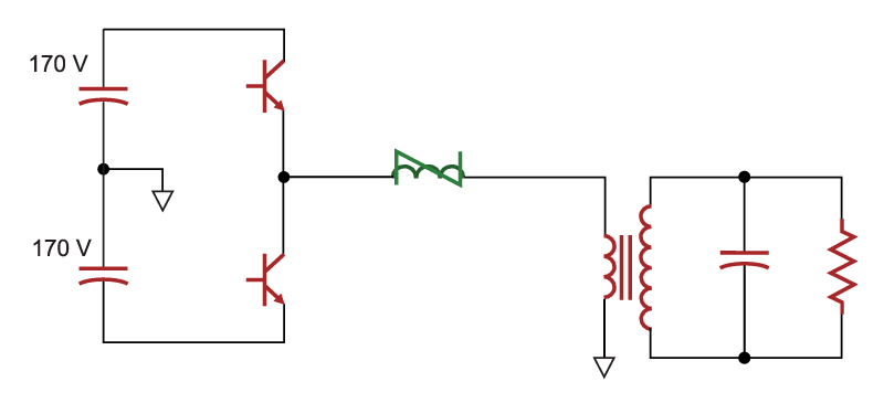
Fig. 1: Half-bridge offline converter driving resonant LC filter with saturable reactor
There were many challenges to this project. First and foremost was the specification.
- Input: 95 to 132 VAC, 60 Hz
- Output: 5000 VAC at 20 kHz.
Furthermore, the output was to be regulated. The application was for a static-eliminator bar inside a copy machine, and the 5000 VAC would produce a corona discharge on the load through which copy paper would pass to have the static charge removed.
This looks like a very daunting task, but at the time I didn’t have enough experience to realize how difficult it should be. Producing a regulated output sinewave is normally something that would be achieved by varying the frequency of the input drive signal, and using the resonant gain characteristics to control the output. This is the more complicated approach.
Surprisingly, however, all of the specifications can be achieved without any control feedback, with the circuit running open loop at a fixed frequency. All that is needed is a nonlinear element, the inductor, which saturated during part of the resonant cycle. This is a form of “ferroresonance� which was the basis of regulated line-frequency ac power supplies for many decades before the advent of modern power electronics. To this day, you can still buy ferroresonant transformers as line conditioners. They are big and very bulky, but they have a reputation for ruggedness and good line isolation for transient events
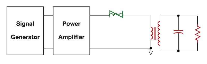
Fig. 2: Resonant LC filter driven by power amplifier and function generator
Ferroresonance is a fascinating field of study. If the circuit is operated above the resonant frequency, there is an intriguing event known as the “ferroresonant jump�. As the input voltage is increased, the output voltage increased in proportion to the input while the resonant inductor current remains below the saturation level of the inductor core. Once it exceeds this level, the output voltage of the circuit “jumps� to a higher value, and remains locked at that value with further increases in the line voltage. Very little further change is observed in the output voltage, and the voltage is essentially regulated automatically.
Initial circuit testing was done with the setup of Fig.2, using a signal generator, and high-voltage tube amplifier. This setup showed all of the characteristics of the ferroresonant circuit, and allowed the simulation problem to be set up properly to explore how the circuit worked.
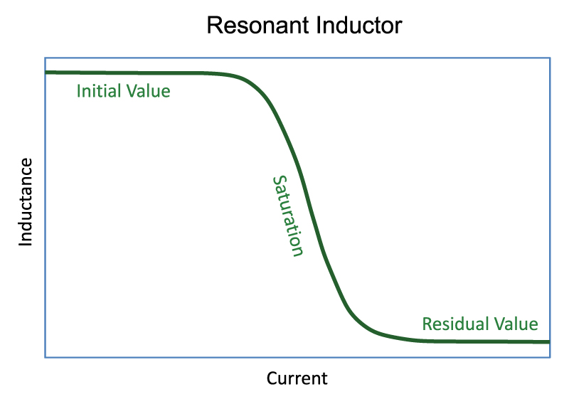
Fig. 3: Saturable inductor characteristics
After many months of writing Fortran code, and running simulations on a mainframe computer (well before the days of the PC) I had achieved an intricate understanding of how the saturable inductor was capable of regulating the output voltage. I could predict where and when the ferroresonant jump would occur, and under what conditions.
The simulator that was written for the circuit did not need the exact characteristics of the inductor to show the regulating effects of saturation. All that was required was a piecewise-linear curve, as shown in Figure 4
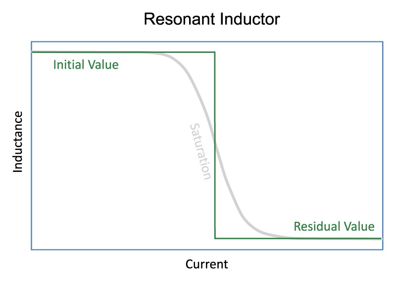
Fig. 4: Simplified saturable inductor characteristics for simulation.
I had certainly satisfied the academic requirements for a senior project after all this simulation and made some interesting new discoveries about the circuit that could be the basis for several research papers.
However, the company who sponsored the work on this converter needed a working product, not a simulation and publication. So, armed with new understanding, I now had to implement the front end of the converter with transistors rather than a signal generator.
Hardware Testing of Ferroresonant Half-Bridge
Nothing I had seen in any simulations prepared me for what happened next with the real hardware. I built what seemed to be a reasonable circuit according to what I had read from the scant information available on the topic. However, within minutes of turning on the switch, and turning up the input voltage, the input transistors blew up â€" quite literally. At the end of the day, I had on my hands a box full of blown-up transistors and went home tired, frustrated, and feeling like I knew nothing about the real world of power electronics. I am sure that many of you have been through the same baptism of fire during your first product development.
Nothing in the data books, or application notes even hinted at how hard this was going to be. Modern application notes continue this trend â€" according to most of them, this kind of work was supposed to be easy, but I certainly didn’t find it that way.
The next few months proved to be a trial of perseverance and learning. Once the initial problems of voltage spikes, current runaway, and transistor cross-conduction were solved with modified drives and timing, thermal issues took over as the dominant failure mechanism. Storage time delay in bipolars, rise and fall time, and switching loss became a very familiar topic to me. Simulation and calculation do not come anywhere close to the real losses encountered since many of the hardware effects were simply too complex to be modeled.
With appropriate cooling added, the input voltage was increased further. Then I got my next hard lesson â€" at a couple of thousand volts, corona started to appear in the transformer, and the circuit failed again. Repeated attempts to wind transformers failed miserably, with every effort resulting in eventual breakdown. I spent many hours in a dark room, watching the circuit and hoping in vain that the familiar blue discharge of corona would not appear â€" but it always did.
I never did solve the problem then with homemade magnetics, and only a vacuum-impregnated transformer finally worked. This had to be built by a serious magnetics vendor who understood the technology thoroughly.
This project was a tremendously valuable lesson in where simulation is useful, and where it is not. Since then, I have never assumed to understand a circuit, or give an opinion on suitability of a design for production without seeing hardware measurements. I was fortunate to run into so many real-world issues early on, since many of them are commonplace.
My design philosophy is this: Get to the hardware stage as quickly as you possibly can. Do not get too deep into simulation without hardware verification, or you will be wasting a lot of time. If customers require simulation as part of a design verification package, the simulation must be refined as you go. In many cases, it is simply not possible to simulate all the effects that are seen in the real circuit. This brings into serious question the point of simulation, and I will continue to try to answer this in future articles. One thing that is certain is that simulation is not a substitute for hardware.
Modern Software
During my first project, no software was available and I had to write my own fast and efficient simulation programs. It was terribly important to understanding how things worked for an unfamiliar circuit. Even if circuit simulation software had been available, the computers of the time would have been far too slow to achieve anything meaningful that would have helped with the real hardware issues.
Thirty years later, computers are incredibly fast with numerous options available for analysis and simulation â€" POWER 4-5-6, Spice, Simplis, MathCad. They all can have a place during project development, but they must not be allowed to interfere with the real work that must be done â€" building hardware and testing it. As you choose your tool to aid in the design process, you must be sure that it will accelerate the design process.
Research and Simulation
In the last few years, I have seen a dismaying new trend coming out of research universities around the world. Students will generate a new theory in control, or a new topology that may look promising. However, rather than building hardware to verify what they have done, they depend on a simulation program like SIMPLIS to provide confirmation of analytical results. Perhaps this is a valuable step in the confirmation process, but it does not begin to substitute for hardware testing.
I would encourage all students who are taking this path to heed the following advice:
Do whatever is necessary to confirm your results with hardware. My time at graduate school was most valuable when working in the hardware lab â€" exploring new circuits, looking at waveforms, and sharing ideas and results with many others doing similar tasks. This is when the best learning is accomplished in a hands-on manner. During the process, you will invariably discover many new effects that complicate the results, but also lead to opportunities for further learning and invention. This rarely happens when running simulators, something that is too easily forgotten with the latest generation of computer experts.
Summary
Simulation has an important role to play in the understanding of circuits, and modeling of the first-order events that will be seen. However, it is no substitute for hardware testing, and you must use simulation to move to the hardware stage as quickly as possible to begin real testing.
In over 30 years of power supply design, testing, and reviews, I have never encountered a situation where an anomalous hardware event or failure was solved by using a simulator. Always, the solution has been found with time in the lab.
References
1. Ridley Engineering Design Center, www.ridleyengineering.com