With the fourth industrial revolution in full swing, manufacturers are focused on a combination of connectivity, automation, machine learning and real-time data processing to reduce costs using fewer people and more equipment
Figure 1: Wireless charging of mobile robots on a factory floor
Harnessing Electromagnetic Induction to Power the Wireless Charging of Industry 4.0 Mobile Robots
Advances in wireless charging have been critical for keeping these robots running, but solutions must be optimized for the specific cost and safety requirements of Industry 4.0 applications. These challenges can be overcome through the proper combination of component selection, coil design and board layout.
Role and Benefits of Electromagnetic Induction
Electromagnetic induction is the principle that enables wireless charging systems to transfer energy from a charging source pad installed on the factory floor to a receiving pad installed on the mobile robot (see Figure 1).
The first step in the electromagnetic conduction process is to pass an alternating current through an induction coil on the transmitter side. This creates an oscillating magnetic field that is then coupled with an induction coil on the receiver side. This produces an alternating electric current in the receiver side coil.
The components required for a wireless charging system range from the transmitter and receiver coils, tuning capacitors and coil drive to diode rectifiers, a DC-DC converter, and transmitter and receiver control circuitry and associated algorithms. A battery-charging circuit is also required.
Implementing a Wireless Charging Solution
Wireless Charging typically requires a higher upfront investment when compared to a wired charging implementation. Moreover, optimizing efficiency and addressing EMI concerns can be challenging. Solutions also must mitigate the safety issues in the event that there is a foreign object between the transmitter and receiver coil that might cause overheating.
Especially important are bill of materials (BOM) cost management and component selection. The first section to evaluate is the wireless power transmitter, where the power switches, resonant capacitors and coil constitute the critical loop for the switching currents in a high-power wireless power system. There are high voltages, currents and switching frequencies in this loop. Achieving desired efficiency, EMI performance and thermal performance while delivering high reliability in a wireless power transfer system requires a combination of efficient PCB layout with proper component placement and routing. There are other challenges to solve related to manufacturing variabilities in the coil. Any coil-to-coil variation that is manifested across products can cause inconsistent behavior in the field, as well as unreliable performance.
Solutions may vary in cost and performance e depending on component selection and board layout decisions. Optimization that can be done to create the most reliable system. The first step is to specify fixed-function devices since they are optimized for performance when compared to general-purpose controllers in a wireless charging solution. These fixed function devices which include wireless charging algorithms, can help accelerate development.
Optimized Solutions Rely on Fixed-Function Devices
Fixed-function devices enable developers to optimize their wireless charging solutions for safety, reliability and efficiency at high power levels. Developers should start by optimizing the transmitter and receiver circuitry that is used to run highly specialized algorithms for wireless-charging communications, power control and Foreign Object Detection (FOD).
Using in-band communication in the wireless charging solution is more cost-effective than out-of-band communications alternatives. To implement Q-FOD, Power transfer can be briefly stopped for a few milliseconds to measure the coil voltage with the fixed function devices high speed peripherals and core. The presence of a foreign object (or not) can be detected by calculating the coil voltage slope when the output FETs are off.
All solution components including controller, FETs, regulators and coils should be chosen based on how well their cost fits within the total system budget. Efficiency will depend on the power control scheme as well as an optimal coil design. Microchip’s WP300 solution, which has been designed to provide system efficiency greater than 90 percent at loads above 100 Watts. This efficiency is measured from the transmitter’s DC input to the receiver’s regulated DC output. The solution can operate at a 12-36V DC input voltage range. On the receiver side, the solution can regulate to a similar voltage range. The reference design’s PCB layout, component placement and PCB stack-up have all been optimized for the highest possible performance (see Figure 2). The PCB’s digital, analog and power sections are isolated to minimize noise coupling.
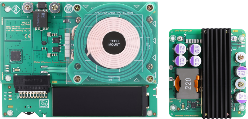
Click image to enlarge
Figure 2: The wireless power transfer reference design above uses a proprietary protocol that implements reliable power transfer with high efficiency and effective FOD. Algorithms are based on extensive R&D and multiple granted patents
To mitigate EMI, the correct control methods must be used in the transmitter, and decoupling capacitors should be used to reduce switching noise and frequency. The use of decoupling capacitors introduces tradeoffs that must be evaluated to optimize the design.
Wireless charging devices that have coil calibration data written to them during product test enable a solution’s coil parameters to be calibrated on the production line during assembly. This improves the consistency of product operation across part-to-part variations while delivering more reliable performance. A final option to consider is creating 1:1 pairing between the transmitter and receiver using secure communications in-band to ensure that receiver devices can only be powered if they are authenticated by the transmitter. Figure 3 includes block diagrams of a 300W transmitter controller and 300W receiver controller that have been optimized to deliver these capabilities.

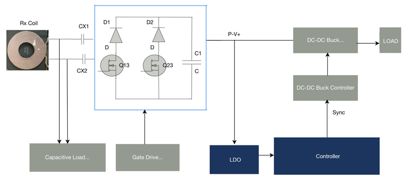
Click image to enlarge
Figures 3a and 3b: The block diagrams above show the transmitter and receiver circuitry of an optimized wireless charging system
Impact of Wireless Charging on the Factory Floor
Using modern wireless charging systems to power mobile robots can increase efficiency and improve productivity. When idle time is used for charging robots, these wireless power solutions also enable continuous factory operation and improve return on investment by enabling the robots to be used for more applications. Human intervention is reduced since the charging process can be automated. Connectors and cables can also be eliminated, reducing maintenance costs while creating a fully contactless solution.
Safety, security and reliability are also improved with wireless charging systems. Safety is improved since there are no connectors that can cause sparks due to short circuits when there is contamination or moisture in them, and because the solutions can detect metal debris and other foreign objects between the transmitter and receiver coil. Security is improved because these systems can implement authentication between charger and robot to avoid unauthorized access. Reliability is improved by using data transfer during charging to increase uptime through predictive maintenance, and because wireless charging systems are easier to maintain and clean on the factory floor than wired alternatives.
This value of Industry 4.0 has been reinforced in recent years with the need to reduce the number of factory workers who can spread communicable diseases like COVID-19. Wireless charging systems will play an increasingly important role in achieving this automation vision by minimizing human intervention. Bringing them to the factory floor will require that best practices be followed in component selection, coil design and board layout. Working with knowledgeable component suppliers on these issues, developers can accelerate and simplify their designs, reduce risk, and fulfill the promise of electromagnetic induction technology. At the same time, they can increase productivity, reduce manufacturing cost and improve safety and security.