High Efficiency, High Density PSM μModule Regulator with Programmable Compensation
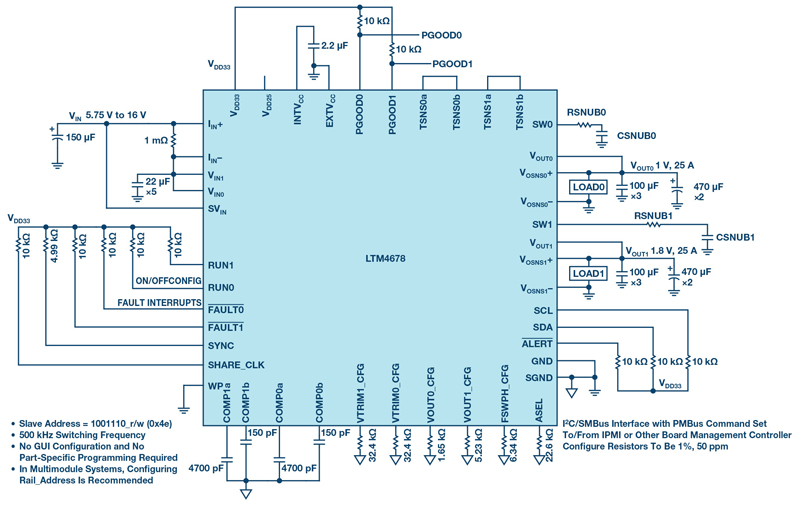
Figure 1. 1V and 1.8 V outputs at 25 A with I2C serial control and monitoring interface.
FPGA boards, as well as prototype, testing, and measurement applications demand versatile and high-density power solutions. The LTM4678 is a dual 25 A or single 50 A µModule regulator with digital power system management (PSM) in a small 16 mm × 16 mm footprint. It features:
- Dual digitally adjustable analog loops with a digital interface for control and monitoring
- Wide input voltage range: 4.5 V to 16 V
- Wide output voltage range: 0.5 V to 3.3 V
- ±0.5% maximum dc output error over temperature
- ±5% current readback accuracy
- Sub-mΩ DCR current sensing
- Integrated input current sense amplifier
- 400 kHz PMBus-compliant I2C serial interface
- Telemetry polling rates up to 125 Hz
- An integrated 16-bit Σ-Δ ADC
- Constant frequency current mode control
- Parallel operation with balanced current sharing
- 16 mm × 16 mm × 5.86 mm CoP-BGA
I2C-Based PMBUS Interface and Programmable Loop Compensation
The LTM4678 is a member of ADI’s power system management (PSM) µModule family, so it can be configured and monitored through a PMBus/SMBus/I2C digital interface. The PC-based LTpowerPlay® tool enables visual monitoring and control of power supply voltage, current, power use, sequencing, margining, and fault log data. The LTM4678 is the first µModule regulator with programmable loop compensation: gm and RTH, which greatly reduces design time, since dynamic performance tuning is done without the hassle of iterative PCB board builds ormodifications.
CoP-BGA Package for Enhanced Thermal Performance, Small Size and High Power Density
A thermally enhanced component on package (CoP) BGA package enables the high power LTM4678 to fit a small 16 mm × 16 mm PCB footprint. Inductors are stacked and used as a heat sink to enable efficient cooling.
Easily Scale to Higher Current with Current Mode Control
The LTM4678 uses peak current-mode control. Current is monitored and controlled cycle by cycle. This enables equal current sharing among phases.
Other Unique Features
- Dual remote output sensing compensates for the voltage drop on traces in high current application
- ±0.5% maximum dc output error over temperature provides additional regulation margin
- Direct input current sense measures the precise input current and power
- Dedicated PGOOD pins provide signal for downstream systems when output voltage is in regulation range
- EXTVCC pin maximizes efficiency at high VIN conditions
Dual-Output Converter (1 V at 25 A and 1.8 V at 25 A)
Figure 1 shows a typical 5.75 V to 16 V input, dual-output solution. The LTM4678’s two channels run with a 180° relative phase shift, reducing the input rms current ripple and capacitor size.
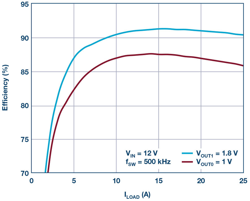
As shown in Figure 2, the total solution efficiency in forced continuous current mode (CCM) is 85.8% at 1.0V/25A output, and 90.4% at 1.8V/25A.
Click image to enlarge
Figure 2. Efficiency of the two outputs.
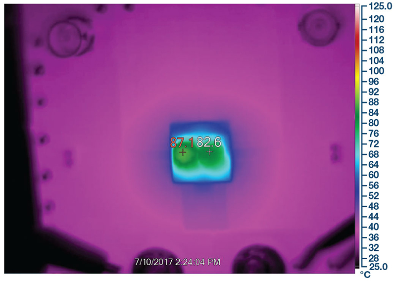
Figure 3 shows the thermal performance of the LTM4678 running at VIN = 12 V, VOUT0 = 1.0 V/25 A, and VOUT1 = 1.8 V/25 A with 200 LFM. Thehot spot (inductor on CH1) temperature rise is 63°C, where the ambient temperature is about 24°C.
Click image to enlarge
Figure 3. Thermal performance of the dual output converter.
Polyphase, Single-Output High Current (12 V to 1 V at 250 A)
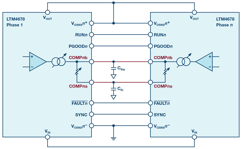
The LTM4678 can be configured as a polyphase single-output converter for higher current solutions. Figure 4 shows a block diagram for connecting multiple LTM4678s. To increase output current, just add additional LTM4678s and connect the respective VIN, VOUT, VOSNS+, VOSNS−, PGOODs, COMPa/b, RUN, FAULT, SYNC, and GND pins together.
Click image to enlarge
Figure 4. Block diagram showing the simplicity of multiphase operation.
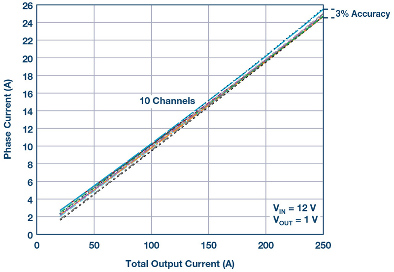
Figure 5 shows the current from each phase when five LTM4678 (10 phases) are paralleled. The maximum current difference among 10 phases is 0.75A (3% based on 25A), representing balanced current sharing.
Click image to enlarge
Figure 5. Current sharing among 5 LTM4678 devices with 10 phases in parallel.
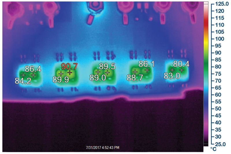
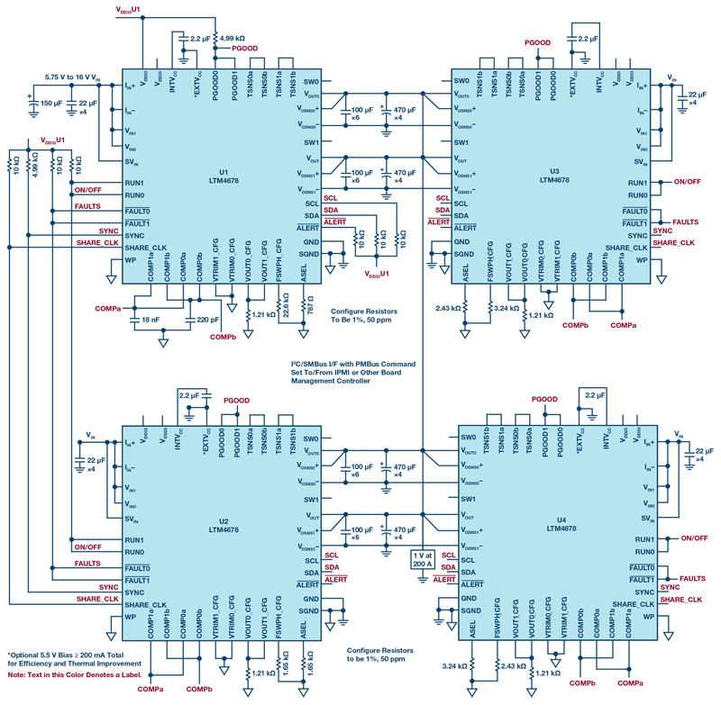
Figure 6 shows the thermal image for the five parallel LTM4678s at 220A output with 450 LFM airflow applied. Maximum thermal difference between the five µModule regulators is 10°C. Figure 7 shows the full schematic for an 8-phase solution.
Click image to enlarge
Figure 6. Thermal performance of multiphase converter.
Click image to enlarge
Figure 7. 8-phase operation with four LTM4678s producing 1 V at 200 A.
Conclusion
The LTM4678 µModule regulator is a versatile high performance power solution that delivers high efficiency and high power in a small 16 mm × 16 mm footprint. The small form factor and ease of use make the LTM4678 ideal for space-constrained designs, such as FPGA boards. Multiple LTM4678s can be operated in parallel polyphase operation for higher current applications, such as those required in telecom and data-com systems, as well as industrial and computer system applications.