Current Sensors for Next Generation EV Charging
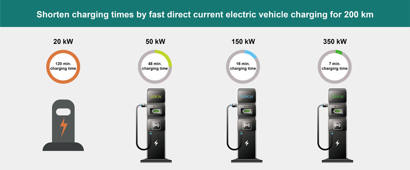
Figure 1: When it comes to charging EVs, there are several methodologies depending on the operating paradigm and available infrastructure
The current generation of Electric Vehicles (EVs) can accept electricity at a much faster rate than previous models, to the extent that current charging stations can’t handle the vehicles' ability to accept a charge.
Unfortunately, many legacy chargers are AC-driven systems, with only a fraction of existing chargers using much faster DC-based power electronics. A modern EV can take several hours to fully charge using old AC-based systems.
This is one reason many are turning to fast-DC charging systems for the home, where the car could be charged to a significant extent in a short period of time. Even a 50-kW system can charge an EV to over half charge in less than an hour. On-board chargers using a standard household connection or commercial wallbox cannot match the speed of these systems.
Levels of ability
Highway and city charging stations are being set up to extend the range and reach of an EV, but the ability to charge quickly, safely, and reliably at home will be a major factor in adoption. Most individual passenger cars remain parked for eight to 12 hours at night, and home charging can be easier and usually less expensive than charging elsewhere.
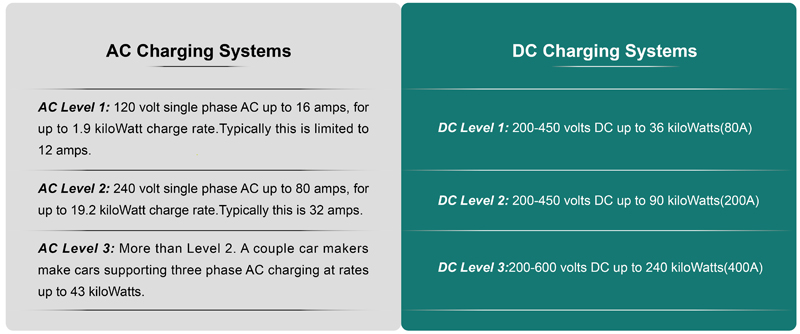
Level 1 battery charging uses a 120 Vac line, and is basically using a standard household outlet as the power source. Level 1 charging gear comes standard on vehicles, using a provided cord with a standard, three-prong household plug. Level 1 charging generally takes 8 to 12 hours to completely charge a fully-depleted battery, and is usually done at the vehicle owner's home overnight.
A Level 2 EV charging circuit uses a 240 Vac, and uses a dedicated 40-Amp charging circuit. Level 2 charging usually takes from 4 to 6 hours to fill an EV battery. Level 2 chargers are usually deployed at curbside kiosks, public parking, and commercial buildings, as they are more expensive to set up. Level 3 technology, also known as DC fast charging, charges through a 480Vdc, and can charge a battery up to 80% in 30 minutes.
When it comes to home-based charging systems, Level 2 Charging stations are currently showing the most promise among the 3 charging levels. By 2027, it is estimated that Level 2 Charging Stations will occupy a major share for EV charging usage. This may be due to the growing emphasis of public and semi-public charging stations for overnight charging, as well as people shifting to the use of Level 2 chargers as private charging stations at their homes.
Click image to enlarge
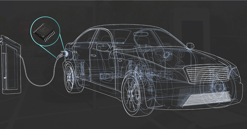
Figure 2. Because of the requirement to first convert AC to DC, AC based chargers require a longer time to charge a vehicle
In an AC charging system, the acceptance rate of the power convertor, which varies by manufacturer, determines the charging speed and overall time needed. This process requires an additional task to complete, as the incoming AC must be rectified, so the charging speed is relatively slow. DC power, on the other hand, bypasses the converter altogether, so the charge can go directly into the battery, speeding up the charging process. DC charging offers advantages in situations where quick battery replenishment is either required or preferred, with the only limiting factor being the connector type used to charge the vehicle.
Since DC Fast Charging bypasses the limitations of the on-board charger and required conversion by providing DC power directly to the battery, charging speed has the potential to be greatly increased. Today, a DC charger with 150 kW can put a 200 km charge on an EV in around just 15 minutes. Charging times are dependent on multiple factors, but many vehicles are capable of getting an 80% charge in about an hour using most currently available DC fast chargers (Figure 3).
Click image to enlarge
Figure 3: Many vehicles are capable of getting an 80% charge in about an hour using most currently available DC fast chargers
With in-home DC fast-charging systems growing as a significant sector of the growing electrical mobility infrastructure, it is important to note that in the crossover space of consumer-oriented capital goods, longevity and reliability compete with cost-effectiveness. With that in mind, that cost-effectively improves the efficiency, safety, and performance of the power conversion system and adds directly to the manufacturer’s bottom line.
There are three main aspects in a modern power conversion system: measuring the current and addressing thermal issues, ensuring tight power-factor correction, and optimizing the system’s frequency management. Not only are they important factors in and of themselves, but they also leverage one another to raise the overall performance of the combined system.
Current measurement
Current measurement, beyond just knowing output, can serve as a means for managing system thermal performance. Managing system thermals via current measurement prevents system damage, by early fault detection, among other aspects. In addition, many applications require either an indication of an out-of-range current condition, or loss of control of system performance in the event of an over-current condition, to properly address potential faults.
Such situations can range from ground faults or other short-circuit events to loading conditions beyond those the system was designed to support. No matter the source, any protection circuitry needs to be comprehensive to ensure that these potentially damaging conditions are not allowed to manifest themselves.
An integrated solution offers footprint savings over a simple op-amp and comparator current-measuring implementation. The size of the implementation will vary depending on the actual components chosen, but it will always be smaller than a solution assembled from individual parts.
Overcurrent detection
Overcurrent detection prevents damage in electronic systems. Fuses are no longer adequate in any manner for advanced electronic systems except to prevent catastrophic failure. Its use as a protection component does not provide information on the actual operating conditions of the system, beyond other undesirable aspects. Many over-current detection solutions can be optimized based on the primary concerns of a given application, be it cost, solution size, measurement accuracy, or alert response time.
Protection of switching circuits from overcurrent conditions and improving the safety of the overall system is paramount. The current-sensing solution developed by ACEINNA is well suited for overcurrent detection, due to its very fast response and large current measurement range. As it is isolated, it could be used in both the high and low side of the solution.
Integration of aspects such as isolation, along with AMR (Anisotropic Magneto-Resistive) sensing and temperature correction, reduces the complexity of the customer design compared to a shunt plus isolated amplifier solution. Additionally, by using an AMR current sensor on the high side, the ground fault of the phase current could be detected (possibly due to wrong wiring, aging etc.), and the overall system could be protected.
Click image to enlarge
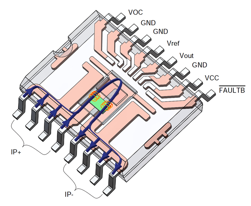
Figure 4: Due to their very fast response and large current measurement range, ACEINNA’s family of Anisotropic Magneto-Resistive current sensors are well suited for overcurrent detection.
Power Quality and Power Factor
Another significant aspect is power quality, which is essential for efficient equipment operation, and the power factor contributes to this. Power factor measures the efficiency of incoming power used, a ratio of active to apparent power.
Poor power factor, say less than 95%, results in more current being required for the same amount of work. Power factor correction (PFC) improves the power factor, and power quality. It reduces the load on the grid, increases energy efficiency, and reduces electricity costs. It also decreases the likelihood of instability and system failure.
Power factor correction is obtained by producing reactive energy in opposition to the energy absorbed by loads such as motors, locally close to the load. This improves the power factor from the point where the reactive power source is connected. In principle, the ideal compensation is applied at the point of load, at the level required in real time. PFC equipment on the low voltage side increases the power available at the secondary of a MV/LV transformer.
There are strict regulations to limit the harmonic distortion permitted on the AC mains line. Hence power factor correction is necessary in the AC/DC inverter front end. This also helps with improving the power factor (PF) number. Since most of the time, isolation between the primary and secondary side of the AC/DC front end module is required, ACEINNA’s current sensors not only simplify the overall system design, but also reduce the cost of implementation.
Switching frequency
The switching frequency is related to bringing regulated power to the point of load. With the continual demand for higher performance, CPUs, DSPs, and other such devices grow more power-hungry. Accordingly, higher power density regulators with minimal PCB footprints have evolved; these use the latest in IC integration, SiC or Gan Switches and packaging.
Increasing regulator frequency reduces the size and board footprint requirements of the associated passives, but experience from legacy hard-switching PWM regulators, says as frequency increases, so do switching losses. These issues are mostly due to high-side losses during turn on and body-diode conduction losses, among other factors. Such losses force limits on the switching frequency of conventional converters and regulators.
Current measurement is critical for any power converter application, and in DC/DC switching applications, it is required to track fast-switching currents to achieve high efficiency. Another important reason to measure the current is to perform a control algorithm to achieve better performance. ACEINNA’s high accuracy and high bandwidth current solutions not only help customers increase the efficiency of the system but also simplifies the current control design due to its high phase margin.
Looking forward
The market for recharging systems for all kinds of battery-based products, not only EVs, demand highly efficient and cost-effective charging methodologies. Although multiple modes and levels of automotive charging systems do exist, fast DC charging is emerging as one of the most preferable forms of EV replenishment. Being able to optimize such systems will ensure success in this new marketplace.
ACEINNA