In modern manufacturing environments, inspection is increasingly constrained by cost control or containment priorities
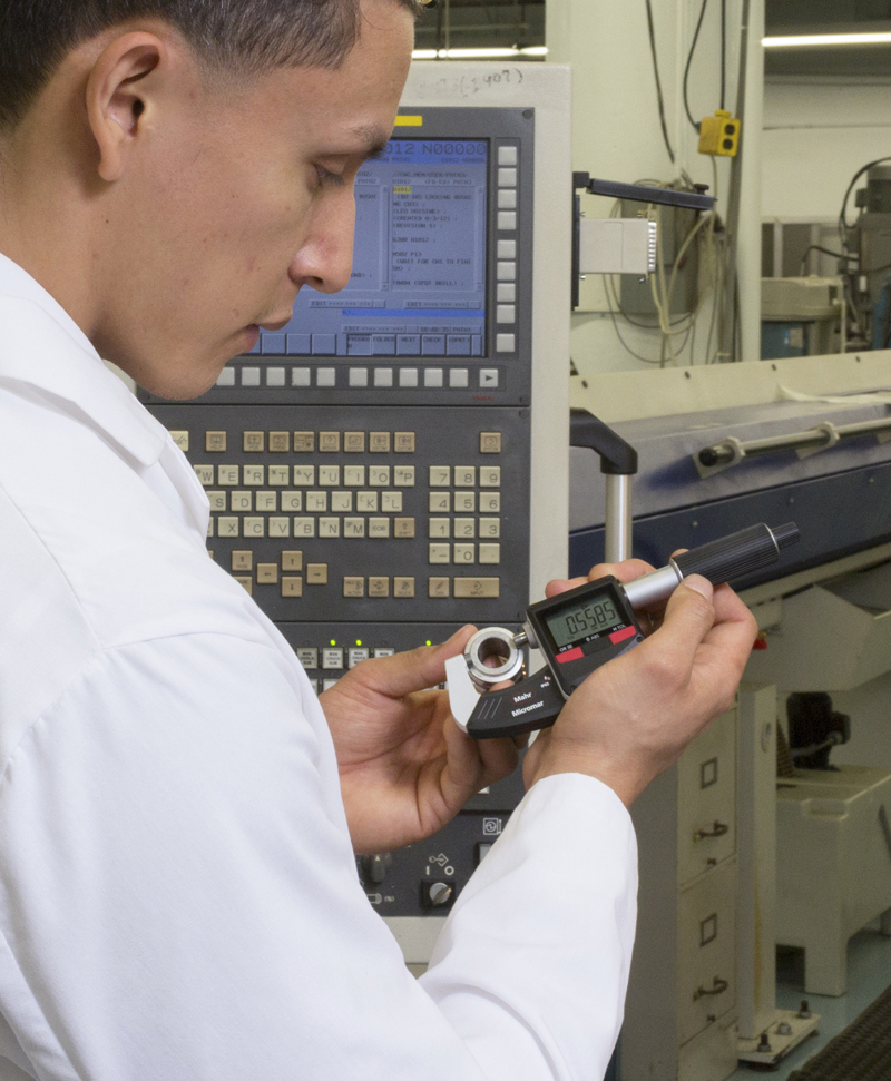
Figure 1: Today’s smart hand tools provide information for machine control and inform the operator of part quality with tolerance indication
In manufacturing, it makes perfect sense to maximize the value of every dollar, but it also means hard choices must be made when selecting handheld gages. For example, myriad issues such as training, warranties, throughput requirements, manufacturing methods and materials, the end-use of the workpiece, and general company policies on gaging methods and suppliers may influence both the effectiveness and the cost of the inspection process.
Many companies have achieved economies of scale by moving inspection, including gaging, from the lab to the shop floor—tight-tolerance measurements that were once performed in a semi-clean room by a trained inspection technician are now being done right next to the machine. As a result, machinists and manufacturing engineers have become more responsible for potential quality issues. Additionally, by having the gaging at the point of manufacture, bad parts can be found immediately and corrections implemented to prevent others from being made.
However, just because hand gages at the point of manufacture have become commonplace doesn't mean that just any gage can be taken onto the shop floor. To assure good gage performance, there are a number of specifications and care issues that need to be addressed.
Gaging Specifications for the Production Environment
First, is the gage designed to help the user get good measurements? A gage with good Gage Repeatability and Reproducibility (GR&R) numbers will generate repeatable measurements for anyone who is trained to use it properly. Gages with good GR&R have a robust look and feel, and part alignment is designed in to make sure the part is held the same way every time and to eliminate the effects of operator influence on part positioning. As a result, technique or "feel" should have minimal impact on results.
Next, is the gage designed to withstand the production environment? Gages designed for laboratory use often cannot cope with the dust and oil present on the shop floor. Features commonly found on solid shop floor gages include: careful sealing or shielding against contaminants; smooth surfaces without nooks and crannies that are difficult to clean; and sloping surfaces or overhangs designed to direct dust and fluids away from the display.
Last but not least, is the gage easy to operate? Machinists often prefer gages that operate like CNC machines; once it has been programmed, push a button and the machine runs, cuts a feature, and is ready for the next part. Gaging should be simple too, requiring as few steps as possible to generate results. If a variety of parts are to be measured on the same gage, it should allow for quick, easy adjustment to the next size. If data collection is required, it should be nearly transparent to the operator using of the gage.
No matter how well protected against contamination, if a gage is used on dirty parts, or in a dirty environment, it will get dirty. At the end of every shift, users should wipe down the master and place it in its storage box. Inspect the gage for loose parts: contacts, reference surfaces, locking knobs, posts, arms, etc. If this is done every day, the life of the gage can be prolonged by years or at minimum, it will make it easier for the calibration department to check it out and verify its operation.
Matching Gage Performance to the Application
Once the key features of the gage have been defined as successful, the capabilities of the many different types of handheld gages available should be considered. While the terms "measuring" and "gaging" are often used interchangeably, there are instances when measuring is appropriate, and others when gaging is the way to go.
What's the difference?
Measuring is a direct-reading process in which the inspection instrument consists of (or incorporates) a scale—a continuous series of linear measurement units (e.g., inches or mm,) usually from zero up to the maximum capacity of the instrument. The workpiece is compared directly against the scale, and the operator counts complete units up from zero, then fractions of units. The result generated by "measuring" is the actual dimension of the workpiece feature. Examples of measuring instruments include steel rules or scales, vernier calipers, micrometers, and height stands. CMMs might also be placed in this category.
Measuring tools like calipers and micrometers are used by machine shops everywhere. Many shops don't have a very high volume of parts so they need tools that give them a lot of flexibility to measure a number of different features relatively quickly and easily. With these types of hand tools and a good set of gage blocks, it should be fairly simple to measure a wide range of parts having tolerances in the order of +/-0.001".
Gages, in contrast, are indirect-reading instruments. The measurement units live not on a scale, but off-site (typically in a calibration lab somewhere), and a master or other standard object acts as their substitute. The workpiece is directly compared against the master, and only indirectly against the measurement units. The gage thus evaluates not the dimension itself, but the difference between the mastered dimension (i.e., the specification), and the workpiece dimension.
Gages bring a whole new level of measuring capability to the user. What might have been a difficult +/-0.001" tolerance for a caliper to measure is now a piece of cake with a comparative gage. Depending on the configuration, tolerances of +/-0.0001" or better are easy for the dedicated gage. Also, gaging tends to be faster, both because it is less general-purpose in nature and because the operator only needs to observe the last digit or two on a display, rather than count all of the units and decimals up to the measured dimension. Because of its generally much shorter range, gaging can also be engineered for higher accuracy (resolution and repeatability) than measuring instruments.
For anything resembling a production run, gaging is almost always required. Conversely, where single part features must be inspected, measuring devices still tend to make more sense. In practice, most shops will find they need some of both types of devices.
Optimal Measuring Instruments
The caliper is an extremely versatile and useful tool for making a wide range of distance measurements (both ODs and IDs). The caliper can span from two inches to four feet, depending on the length of the scale. External measurements are made by closing the jaws over the piece to be measured, while internal measurements are made by opening up the inside diameter contacts.
However, while the caliper is a versatile tool, it is not one of the most precise. Skill is required for positioning the tool and interpreting the measurement result. As the user develops a "feel" for the tool, the measurement results will become more consistent. The digital caliper may take some of the guesswork out of reading the measured value, but it still requires skill on the part of the operator to apply the tool properly to the dimension being measured.
A small step up in accuracy and performance—but with a shorter measuring range—is the micrometer. The basic micrometer is probably the second most popular and versatile precision handheld measuring tool on the shop floor. While the most common type is the outside diameter style, the same measuring principle can also be used for inside diameters, depths, and grooves. With so many options for holding the spindle and alternate contact points available, micrometers can satisfy an endless number of measurement applications.
The biggest problem with micrometers (as with calipers) is that measurements are subject to variation from one operator to another due to "feel" or inconsistent gaging force, and other subjective factors. The micrometer is a contact instrument and sufficient torque must be applied to the micrometer barrel to make positive contact between the part and the instrument. In order to eliminate the "feel" part of the measurement, designers of micrometers have incorporated a ratchet or friction thimble mechanism. This is an attempt to assure more consistent contact pressure and eliminate human influence.
Traditionally the use of the micrometer was a bit time-consuming as adjusting the micrometer to various sizes was a significant chore. The traditional rotating spindle had to be fine enough for good resolution but created a lengthy process to adjust to multiple sizes. Today, some digital micrometers incorporate sliding spindles that make moving to other sizes five times faster than traditional rotating spindles.
Thus, there are some constants with both calipers and micrometers. On one hand, they are versatile and can measure a wide range of different parts. On the other, their accuracy is at the mercy of the operator using them.
Comparative Gages
When a job gets into an area where accuracies are within 0.0005" tolerance, it enters into the region where a comparative gage—such as comparative snap gage, mechanical or air ID/OD gage—is an optimal tool.
For example, if an operator is checking a shaft diameter on the CNC lathe after the manufacturing process is complete, micrometers may be the instrument of choice, and it’s possible to resolve to 0.00005" or so. The issue with this is unproductive time for the operator using a micrometer that has to be aligned and adjusted for each size to be measured; more moving then measuring. A better choice would be an adjustable snap gage.
Click image to enlarge
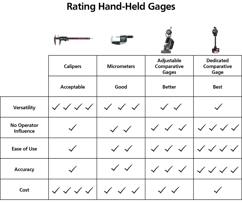
Figure 2: Knowing the gage capabilities allows one to get the best value from the measuring process
Insert a snap gage onto a workpiece and it is easy to see how these extremely effective, fairly simple OD gages got their name. Once the part is pushed through the leading edge of the contacts, the part slips easily back against the backstop, contacting it with a good, healthy "snap."
Snap gages can be handheld to measure workpiece ODs while still on the machine, or can be mounted on stands for use with small parts. The heart of the tool is a simple C-frame casting, and measurements rely upon a direct in-line 1:1 transfer of motion. These factors make snap gages simple, reliable and fairly inexpensive.
With a standard dial indicator installed, the measuring range of an adjustable snap gage is typically .020", with a resolution of .0001." But there's no rule that says an adjustable indicating gage has to have a mechanical dial indicator. With a good digital indicator, a resolution of 20 microinches can be achieved for tolerance measurements tighter than .0005".
Aside from the higher performance of the snap gage, other key features include the speed of measurement and the lack of operator influence. There is no need to adjust the gage to the right size, assure the gage is square to the part, or to apply the right force on the part. It's all built in. Thus, snap gages improve performance through speed and accuracy.
For example, what if the operator needs to measure a bore tolerance to +/-0.0002", on the machine and in a machine shop environment? Notice the trend when the measuring tool moved from the micrometer to the mechanical snap gage: it went from an operator-influenced tool having a measuring range of about an inch to a comparative gage having a total measuring range of 0.020". Less range generally means better performance.
Click image to enlarge
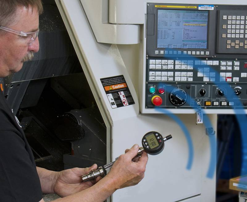
Figure 3: A fixed plug comparative gage allow the operator to get the best measurement with no operator influence
To achieve accuracy in measuring tolerances in the +/-0.0002" range, while still measuring them quickly, a fixed variable gage is required. In this case a mechanical plug gage—generally with 0.003" total measuring range, but one that can get performance resolution to 10µ" or better—can be just as fast as the mechanical snap gage.
Documenting the Results
Digitalization has changed the manufacturing world, and industry is increasingly shaped by the internet and modern technology. The manufacturing industry is facing a significant change as information is now a matter of course, accessible to everyone, and no longer a privilege.
About 35 years ago, the concept of data collection for process control took a major leap forward. With a digital signal available from many handheld gages, it became possible to transfer information via cable directly from a digital caliper, digital micrometer or digital indicator to a data collector. This made it much more practical to make process-control decisions based on statistical analysis.
Since it is now common to check parts at the point of manufacture with hand gages connecting them to a computer via a cable, data collection is the norm. Today's hand tools and digital indicators have data output built in, and collecting data is easy and very cost effective. However, having the wires at the point of manufacture can be a bit of a hazard–either to the gage (cables getting hung up on something) or to the operator by interfering with the normal routine.
The next generation of factory automation aims to take data collection to new levels. From monitoring processes all along the manufacturing progression, to collecting and storing data from the individual measurements, to the offsets sent to the machines to the production results, a lot of data needs to be collected. It has to be easy and transparent to the operator–with no additional work to delay the process and hinder data collection.
To accomplish this, small transmitters are now being built into digital calipers, digital micrometers and digital indicators on gages that enable them to transmit data to a computer. Each integrated transmitter in the measuring tool uses a slightly different signal coding that allows as many gaging stations as possible to communicate to a single computer simultaneously. Today, these transmitters are not that much more expensive than data cables, making the cost more than justifiable when cabling alone won't get the job done.
This technology is ideal for the in-process/right-at-the-machine-tool application. Transmitted wirelessly into the machine tool's controller, the data can be used as part of the calculation for offsetting. Thus, as the operator measures the parts, the data is used to assign the proper offsets, greatly improving the quality and throughput of the machine tool. Out-of-spec parts are virtually eliminated, and the ability of the machine to make parts to the desired dimensions is greatly improved.
Click image to enlarge
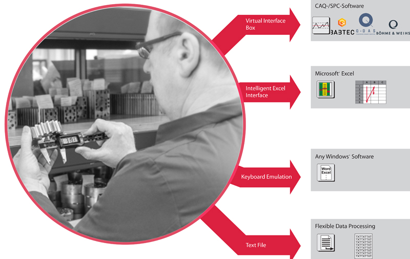
Figure 4: Hand gages today should be smart enough to provide measured results and gage identification to be an integral part of the Factory of the future
Now, with these transmitters, very large parts can be measured where they sit, or parts can be measured in the machine tool without having cables get caught in the tooling. Additionally, the tools provide visual feedback by generating a signal to the operator that the transmission was received and acknowledged by the computer. This is virtually instantaneous so as not to slow the operator down, and most transmitters can be configured to provide a go or no-go signal to the user depending on whether the part is within tolerance.
At the same time, the data can be stored for long-term archiving in the cloud, recording when the part was measured and by whom. It can also be used for tracking and improving operator throughput.
Today the next revolution is rising, with a combination of digital gaging for accurate shop floor measurement, unrestricted wireless transmission of reliable data, and statistics for process control. Combined with the way machines, robots, inventory and material handling systems are now talking together, we truly are getting closer to the fourth industrial revolution.


