How to Maximize Your Wireless Sensor's Runtime
.jpg)
Battery runtime is a critical feature of remote wireless sensors
Battery runtime is a critical feature of remote wireless sensors. Wireless sensors are becoming ubiquitous, penetrating the most diverse applications like home automation (Figure 1), activity monitors, remote sensor nodes, and tire pressure monitors, to mention a few broad categories. Runtime requirements, ranging from one to twenty years, pose a serious challenge to the design of these mobile devices. This design solution will first review a few cases of runtime challenges. Secondly, it will discuss a typical implementation of a wireless sensor system and its shortcomings, and lastly, it will present a new ultra-low-power, RF ISM transceiver that helps maximize battery runtimes for remote wireless sensors.
Runtime Requirements
As an example, wireless magnetic window alarms and wireless locks are becoming more popular in homes and hotels. They are required to run for at least one year on a single battery. In other examples, remotely located meter readers that monitor water and water leaks, earthquakes, gas, humidity, and temperature need to run autonomously for up to 20 years. In each case, the remote system needs to be small and inexpensive, running on very small batteries withlimited capacity, often using only a fraction of an ampere hour (Ah). To meet such daunting runtime requirements, the designer must wisely use every Coulomb in the sensor battery.
Typical Sensor System
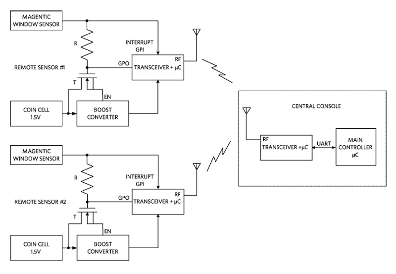
A typical wireless magnetic window alarm sensor system (remote sensor subsystems and central console) is shown in Figure 2. The 1.5V coin-cell battery powering the remote sensor subsystem is regulated by a boost converter. The remote sensor subsystem is in deep sleep mode most of the time, with the boost converter and the transceiver in shutdown. Whenever the magnetic sensor activates, the subsystem is awakened (pullup resistor R and transistor T) and an alarm signal is sent to the intelligent transceiver to process and transmit the alarm to the central console.
Click image to enlarge
Figure 2. Functional Diagram - Wireless Magnetic Window Alarm SensorSystem
During the time the remote sensor is in deep sleep mode, it is required to consume as little power as possible. During regular wake-up and infrequent transmission times, it can draw short bursts of current up to 100mA.
The wall-powered central console’s transceiver wirelessly communicates with each subsystem in the building or in the field. Its transceiver communicates with the main controller CPU, which is responsible for controlling the entire system, via UART.
Battery Runtime
Let’s assume that the coin-cell battery has a 150mAh capacity and the runtime requirement is 2 years. The math is very simple: thesensor operation must be managed so that its average current consumption does not exceed 8.5µA (8.5µA x 365d/y x 24h/d x 2y = 150mAh)! That’s not a lot to get by with.
Typical Solution
A typical solution available today is one that consumes a miserly1µA in deep sleep, which still robs 12% from the overall battery runtime! It becomes evident that each component in the sensor needs to do much better to reduce the runtime loss to more acceptable levels. Ideally, if the remote sensor stays one order of magnitude below this level (100nA), then the runtime loss will be reduced to a more acceptable 1.2%.
Ultra-Low Power Transceiver
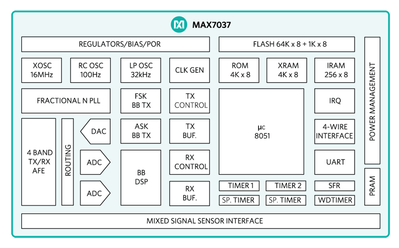
The MAX7037sub-1GHz, ultra-low-power, RF ISM transceiver can meet such a stringent requirement. Figure 3 shows its functional diagram.
Click image to enlarge
Figure 3. MAX7037 Functional Diagram
The MAX7037 is a high-performance, quad band multichannel transceiver with an integrated 8051 microcontroller, flash memory, and sensor interface. It supports the standard ISM bands in the 300MHz to 930MHz range with output power up to 10dBm. The supply voltage runs from 2.1V to 5.5V, enabling it to cope with a variety of energy sources, such as solar cells, electromechanical, or thermoelectrical energy. In Figure 2, the MAX7037 takes the place of each “TRANSCEIVER +µC” block. Hardware-implemented transmit-and-receive routines enable a high-efficiency transceiver system for wireless fail-safe multiband/multichannel communication with advanced FSK (frequency shift keying) and ASK (amplitude shift keying) protocol features. Sleep modes allow easy implementation of low-power applications with fast reaction times.
The Wireless Unit’s Ultra-Low Power Solution
In an event-driven wireless sensor application, the MAX7037 is in deep sleep mode most of the time. In this mode, the current consumption is 100nA (max). When an event is sensed, the sensor signals the microcontroller, typicallythrough an interrupt. A short data packet is formed by the microcontroller and transmitted at the specified frequency. The packet needs to contain some identifier of the sensor like a flag byte indicating its status. It also needs error detection or some sort of checksum or other error-detecting code that applies to the contents of the packet. In addition, the first byte of the packet is the number of bytes in the payload of the packet. Other than the requirement that the first byte indicates the length of the payload, there is no restriction on the contents of the packet payload.
The RF frequency used can be selected from one of the standard sub-GHz ISM frequencies; for example, 315MHz or 868MHz. Depending on which part of the world the system is deployed, the ISM band from that region should be used. If there is a choice of frequencies, the most desirable is the lowest frequency used in buildings since lower frequency signals will propagate better through walls. However, interference considerations may dictate the choice of frequency.
Using our earlier remote wireless magnetic window alarm sensorexample, the MAX7037 reduces the runtime loss from 12% (3 months) down to 1.2% (9 days)!
nanoPower Boost Converter
The MAX17222nanoPower boost converter is also ideal for this application. With its 400mV of minimum input operation, it can draw the last drop of energy out of the 1.5V battery. It also provides a 0.5A peak inductor current limit and a selectable output voltage that uses a single standard 1% resistor. Its novel True Shutdown mode yields leakage currents in the nanoampere range (0.5nA typical), making this a truly nanoPower device.
Central Console
The central console is always on. The main controller CPU periodically polls the co-located MAX7037 to check if a packet has been received. When the packet is received, the CPU confirms the contents are error-free, and if so, broadcasts an ACK (Acknowledgement) packet. When the MAX7037 in the remote subsystem receives an ACK with its ID, it goes back into deep sleep mode. If the packet from the subsystem has an error, the main controller CPU will instead send a Negative Acknowledgement (NAK). If an ACK is not received within a certain timeout period or a NAK is received, the subsystem controller will resend the original packet. The handshaking protocol described is one possible alternative. When using FSK modulation, the MAX7037 can transmit data up to 125kbps.
Conclusion
We discussed the extremely tough requirements for battery runtime in many wireless sensor systems. We reviewed a typical wireless application system which wastes 12% of battery life due to excessive leakage in deep sleep mode. We showed how the use of the MAX7037 reduced the runtime loss from 12% (3 months) down to 1.2% (9 days)! The MAX7037, thanks to its ultra-low, 100nA deep sleep current, cuts the leakage dramatically and helps achieve the long battery runtimes required by this class of applications.
In turn, the MAX17222 nanoPower boost converter, with its True Shutdown mode,provides the ideal power boost for the MAX7037 transceiver.