Author:
Szukang Hsien, Executive Business Manager, Automotive Business Unit; Maxim Integrated
Date
07/02/2020
 PDF
PDF
Click image to enlarge
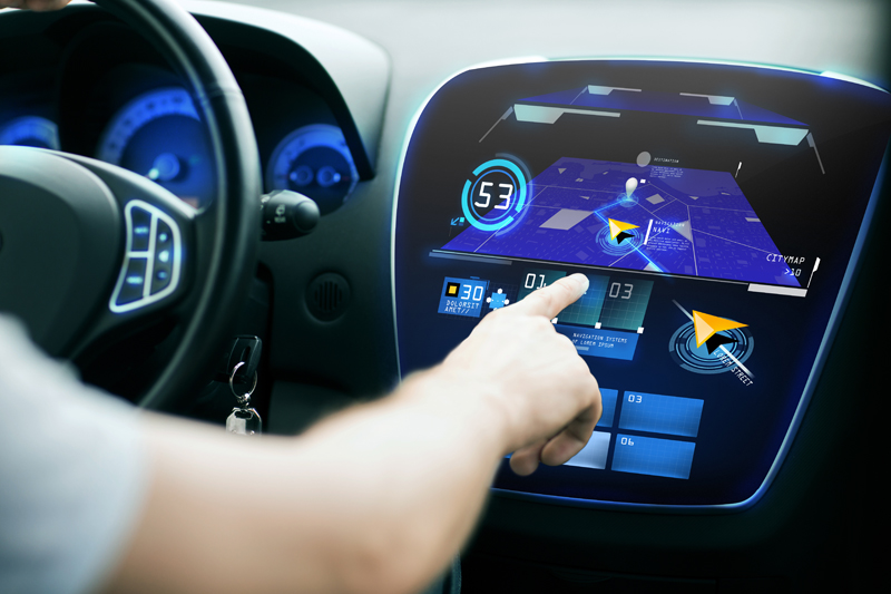
Figure 1. Modern vehicles boast more displays than ever. Given the safety-critical information delivered via displays, it’s imperative for them to meet automotive functional safety standards. Photo courtesy of Syda Productions/Shutterstock.com
It’s becoming more common these days to step inside a vehicle and be greeted with a touchscreen that’s larger than a tablet computer. The screen, serving as the center information display (CID), might share data such as the car’s speed, driving directions, preset radio stations, the driver’s phone book, the location of surrounding vehicles, and, for electric vehicles, the remaining charge. As automotive displays get bigger, they’re also getting sharper, much like TV screens. Analysts are projecting healthy market growth in displays greater than 8 inches, with the potential for in-vehicle screens as large as 49 inches becoming a reality by 2021. 4K and, eventually, 8K resolutions will become standard, while higher contrast technologies are also coming into play. What’s more, many vehicles already have up to 8 displays inside, and cars with up to 12 displays are on the horizon to accommodate the CID, heads-up display (HUD), the instrument cluster, mirror replacements, and more.
With so much riding on the clarity and reliability of these displays, what’s needed from a design standpoint to ensure that your modules will meet automotive functional safety standards? In this article, we’ll guide you through the qualities to seek in light-emitting diode (LED) backlight drivers and automotive power management ICs (PMICs) in order to produce large, razor-sharp vehicle displays.
Common Challenges in Display Module Design
Thin-film transistor (TFT) liquid crystal display (LCD) technology is commonly used in automotive displays, especially for the center stack and the instrument cluster. These displays feature tiny switching transistors and capacitors arranged in a matrix pattern on the display glass. The TFT element acts like a switch, while the liquid-crystal element serves in a role similar to that of a capacitor. When the switches turn on, the signal on the source line is added or recorded on the liquid-crystal capacitor. To produce the display, the source line signals the capacitor (in the form of voltage) to control the deflection angle of the liquid-crystal molecule. The holding capacitor can be connected in parallel with the liquid-crystal capacitor to improve its retention characteristics. The gate line controls the TFT ON and OFF. When the switch is off, it prevents the signal from leaking out of the liquid-crystal capacitor.
Aside from achieving functional safety compliance (which we’ll discuss in a separate section), let’s first take a look at several common challenges you may encounter when designing automotive display modules.
· Preventing flickering in cold-crank conditions: Obviously, flickering is quite undesirable because it interferes with the integrity of the display. However, when a vehicle starts up from a cold state, the car’s battery voltage drops as the engine cranks due to the very low ambient temperature, which can lead to flickering in the display. The LED driver powering the LEDs in the display backlight must be equipped to handle the voltage drop to prevent flickering.
· Providing higher current for larger displays: The larger the display, the more current needed to drive the voltages to power the LEDs. For small screens, a timing controller (TCON) easily supports the current supply requirements. But displays over eight inches need a separate TFT bias or PMIC. Generally, displays that are 8 to 14 inches, with LEDs 10-11 in series with 4 in parallel, need up to 150mA per channel.
· Achieving the right levels of dimming to allow a readable screen under different ambient lighting conditions: when a car is traveling through a very bright, sunny environment, its displays will need more current to deliver the visibility the driver will need. Conversely, if the car is going through a dark area, like a tunnel, that high level of current will result in screens that are too bright. So, the current levels need to be adjustable to dim the display to a level that is readable.
· Passing electromagnetic compatibility requirements: For vehicles, electromagnetic interference (EMI) stems from internal and external sources of RF electrical noise and can compromise display performance. LED backlight drivers that provide features like spread-spectrum frequency modulation, phase-shifting, and gate slew rate control can help reduce EMI.
· Reducing BOM costs and solution size: Of course, cost and solution size are on the minds of many automotive engineers. Small components integrated with multiple functions can help meet these targets.
Why Do Displays Need to Meet Functional Safety Standards?
While you’re backing your car out of a driveway, you want the display showing what the rear camera is seeing to be as sharp as possible. Frozen images or flickering screens could cause you to miss a passing pedestrian or cyclist, for instance. Similarly, if you’re driving along a very dark road at night, you don’t want a screen that will be too bright to see. And, especially for HUD or cluster applications, it’s critical that the same illuminance is maintained even when the LED strings in the lighting systems have errors. These are just a few scenarios that illustrate why functional safety is important for automotive displays.
Click image to enlarge
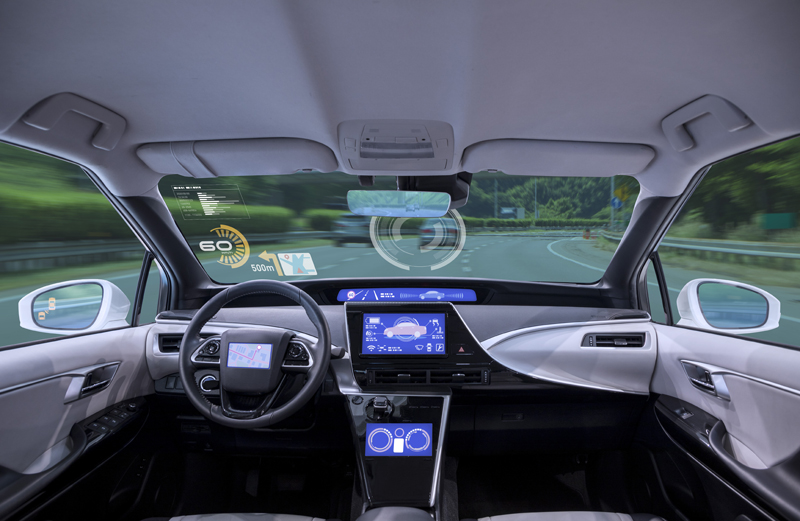
Figure 2. To demonstrate that they are functionally safe, automotive displays must achieve ASIL B compliance. Photo courtesy of metamorworks/Shutterstock.com
ISO 26262 provides an international standard for functional safety of automotive electronic/electrical systems. An important component of ISO 26262 is the Automotive Safety Integrity Level (ASIL), which classifies the inherent safety risk in an automotive system. There are four ASIL levels, each determined by these factors: severity (injuries), exposure (probability), and controllability. Automotive displays are typically in the realm of ASIL B (ASIL D is the most stringent level). In an instrument cluster display, the TFT bias for power management and the LED backlighting driver provide examples of two blocks that should comply with ASIL B guidelines.
The TFT bias consists of AVDD and NAVDD voltages for the TFT source driver, VGON and VGOFF voltages for the TFT gate driver and, sometimes, VCOM voltage for the LCD backplane (which is needed if TCON cannot support the current requirements). This block also has an I2C interface and fault pin for communicating with the microcontroller. Some common TFT bias fault scenarios include: VCOM out of range, overvoltage situation at VGON voltage, and fail-safe operation with an open enable pin. For ASIL B compliance, the TFT bias block should ideally have:
· I2C (the data signal and the clock signal) and the fault pin with the microcontroller for performing setting adjustments and diagnostics on each rail
· Undervoltage and overvoltage monitoring on each rail
· Fixed voltage through internal resistors or adjustable voltage through I2C
· Redundant reference
· Fault enable for additional redundancy
For the LED backlighting driver, the input typically connects directly to the car battery, which has voltage protection when the output is short. The output can either be a boost or single-ended primary-inductor converter (SEPIC), depending on the number of LEDs per string. Communication with the microcontroller is via an I2C interface and the fault pin. The microcontroller reads the register through I2C to determine any errors. Common LED driver fault scenarios include: string 1 with LED open and string 1 with LED short. ASIL B features of an LED driver include:
· I2C (the data signal and the clock signal) and fault pin with the microcontroller for performing setting adjustments and diagnostics on each rail
· Output voltage measurement
· LED current measurement per string
· Fault enable for redundancy
· Redundant reference
Choosing the Right Power Management IC
There are a variety of power management ICs for automotive displays that are designed to comply with ASIL B. Aside from ASIL B requirements, by carefully considering the features of automotive power management ICs, you can address the challenges we’ve outlined earlier regarding the design of display modules. For example, seek diagnostic capabilities such as open/short LED detection, input current measurement, and boost output undervoltage and overvoltage, as well as capabilities such as voltage protection and power system monitoring.
Summary
Carmakers are incorporating bigger and more displays into their vehicles, and these displays are providing drivers with essential information about their surrounding environment, their car’s performance, and more. That’s why functional safety has become an important criteria for automotive displays. Automotive power ICs designed with capabilities like redundancy and diagnostic monitoring can go a long way to ensure that displays in critical applications like ADAS, center information displays, and side mirror replacements will work as intended in all of the environments in which drivers will take their cars.