IC Eases Design of 48 V/12 V Dual Battery Automotive Systems
This is a necessary and crucial step in the long and arduous journey to the fully autonomous passenger vehicle
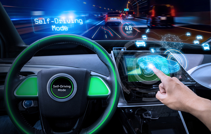
Figure 1. Next-generation cars will be powered by a 12 V and a 48 V battery
The future of 48V/12V battery systems in automobiles is just around the corner. Most of the major automobile manufacturers across the globe have been working on proving out their systems for the past few years and it is evident that their implementation will be relatively near term. This is a necessary and crucial step in the long and arduous journey to the fully autonomous passenger vehicle that does not require a human at the controls and has true autonomous driving. Nevertheless, this doesn’t mean the 12 V battery is going away; there are far too many legacy systems in the installed vehicle base for this to occur. This means that autonomous cars will have both a 12 V battery and a 48 Vbattery.
This fact means that the vehicles’ internal systems will either run off the 48 V lithium-ion (Li-Ion) battery or the 12 V sealed lead-acid (SLA) battery—but not both. Nevertheless, in addition to having two separate charging circuits for these individual batteries due to their respective chemistries, there must also be a mechanism that allows charge to move between them without causing any damage to the batteries or any of the systems within the vehicle. Moreover, having two batteries also allows for redundancy should one of them fail during operation.
While this certainly complicates the design of the various electrical subsystems within the vehicles, there are some advantages to be gained. According to some auto manufacturers, a 48 V-based electric system results in a 10% to 15% gain in fuel economy for internal combustion engine vehicles, thereby reducing CO2 emissions. Moreover, future vehicles that use a dual 48V/12V system will enable engineers to integrate electrical booster technology that operates independently of the engine load, thereby improving acceleration performance. Such compressors are already in the advanced stages of development and will be placed between the induction system and the intercooler, using the 48V rail to spin-up the turbos.
Globally, fuel economy regulations have been tightening, while autonomous driving capability with connectivity continues to proliferate in new automobiles. Accordingly, the 12 V automobile electric system has reached its usable power limit. Simultaneously, as if these changes are not already enough, there has been a significant increase in automotive electronic systems. These changes, coupled with related demands for power, have created a new spectrum of engineering opportunities. Clearly, the 12V lead-acid battery automotive system with its 3kW power limit must be supplemented.
Furthermore, there are new automobile standards that impact how these systems need to work. A newly proposed automotive standard, known as LV148, combines a secondary 48 V bus with the existing automotive 12 V system. The 48 V rail includes an integrated starter generator (ISG) or belt start generator, a 48 V Li-Ion battery, and a bidirectional dc-to-dc converter, which can deliver tens of kilowatts of available energy from the 48V and 12V batteries. This technology is targeted at conventional, internal combustion automobiles, as well as hybrid electric and mild hybrid vehicles, as auto manufacturers strive to meet increasingly stringent CO2 emission targets.
New Power Solution for 48 V/12 V Battery Systems
This new standard requires the 12 V bus to continuously power the ignition, lighting, infotainment, and audio systems. Whereas, the 48 V bus will power active chassis systems, air conditioning compressors, adjustable suspensions, electric superchargers, turbos, and even regenerative braking.
The implementation of an additional 48 V supply network into vehicles is not without significant impact. Electronic control units (ECUs) will be affected and will need to adjust their operational range to the higher voltage. This will necessitate that manufacturers of dc-to-dc converters will also need to introduce specialized ICs to enable this high power transfer.
Accordingly, Analog Devices’ Power by Linear (PbL) Group has designed and developed a few dc-to-dc converters that can enable this energy transfer with very high efficiency to conserve energy while simultaneously minimizing the thermal design aspects.
The need for a bidirectional step-down and step-up dc-to-dc converter that goes between the 12 V and 48 V batteries is clearly required. Such converters could be used to charge either of the batteries while simultaneously allowing both batteries to supply current to the same load if required in the system. From a legacy perspective, these initial 48 V/12 V, dual battery, dc-to-dc converter designs used different power components to step-up and step-down the voltage.
However, ADI’s PbL group recently introduced the LT8228, a bidirectional dc-to-dc controller that uses the same external power components for step-up conversion as it does for step-down conversion.
Click image to enlarge
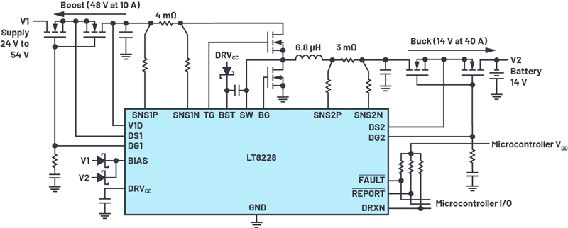
Figure 2. LT8228 configured in a simplified, bidirectional battery backup system
The LT8228, as shown in Figure 2, is a 100 V bidirectional constant-current or constant-voltage synchronous buck or boost controller with independent compensation networks. The direction of the power flow is automatically determined by the LT8228 or is externally controlled. The input and output protection MOSFETs protect against negative voltages, control inrush currents, and provide isolation between terminals under fault conditions such as switching MOSFET shorts. In step-down mode, the protection MOSFETs at the V1 terminal prevents reverse current. In step-up mode, the same MOSFETs regulate the output inrush current and protect themselves with an adjustable timer circuitbreaker.
Furthermore, the LT8228 offers a bidirectional input and output current limit as well as independent current monitoring. Masterless, fault-tolerant current sharing allows any LT8228 in parallel to be added or subtracted while maintaining current sharing accuracy. Internal and external fault diagnostics and reporting are available via the fault and report pins. The LT8228 uses a 38-lead TSSOP package.
The LT8228 is a 100 V, bidirectional, peak current-mode synchronous controller with protection MOSFETs. The controller provides a step-down output voltage, V2, from an input voltage, V1, when in buck mode or a step-up output voltage, V1, from an input voltage, V2, when in boost mode. The input and output voltage can be set as high as 100 V. The mode of operation is externally controlled through the DRXN pin or automatically selected. In addition, the LT8228 has protection MOSFETs for the V1 and V2 terminals. The protection MOSFETs provide negative voltage protection, isolation between the input and output terminals during an internal or external fault, reverse current protection, and inrush current control. In applications such as battery backup systems, the bidirectional feature allows the battery to be charged from either a higher or lower voltage supply. When the supply is unavailable, the battery boosts or bucks power back to thesupply.
To optimize transient response, the LT8228 has two error amplifiers: EA1 in boost mode and EA2 in buck mode with separate compensation pins VC1 and VC2, respectively. The controller operates in discontinuous conduction mode when reverse inductor current is detected for conditions such as light load operation. The LT8228 provides input and output current limit programming in buck and boost mode operation using four pins: ISET1P, ISET1N, ISET2P, and ISET2N. The controller also provides independent input and output current monitoring using the IMON1 and IMON2 pins. Current limit programming and monitoring is functional for the entire input and output voltage range of 0V to 100V.
Furthermore, the LT8228 provides masterless, fault-tolerant output current sharing among multiple LT8228s in parallel, enabling higher load current, better heat management, and redundancy. Each LT8228 regulates to the average output current eliminating the need for a master controller. When an individual LT8228 is disabled or in a fault condition, it stops contributing to the average bus, making the current-sharing scheme fault tolerant.
Additional features include:
- Feedback voltage tolerance: ±0.5% over temperature
- Bidirectional programmable current regulation and monitoring
- Extensive self-test, diagnostics, and fault reporting
- Programmable fixed or synchronizable switching frequency: 80 kHz to 600 kHz
- Programmable soft start and dynamic current limit
- Masterless, fault-tolerant current sharing
Conclusion
The LT8228 brings a new level of performance, control, and simplification to 48 V/12 V, dual battery, dc-to-dc automotive systems by allowing the same external power components to be used for step-down and step-up purposes. It operates on demand in buck mode from the 48 V bus to the 12 V bus or in boost mode from 12 V to 48 V. When starting the car or when additional power is required, the LT8228 allows both batteries to supply energy simultaneously to the same load. This gives power conversion designers a feature rich, bidirectional converter that can easily configure 12 V and 48 V battery systems, which will be required for the fully autonomous vehicles of the near-future.