Impedance Matching and the Selection of Transformers

To ensure optimal performance, systems rely on a process called impedance matching
Figure 1. Audio Applications Photo Montage
Many electronic circuits in audio applications, data networks, communications and others require transmitting an AC signal from a source to a load while minimizing distortion and maximizing power transfer (Fig 1).
To ensure optimal performance, these systems rely on a process called, “impedance matching”. In this article, we’ll examine why impedance matching is so important, how it works, and how it can be easily implemented during the system design phase through proper impedance matching and transformer selection.
What is impedance? Electrical impedance is a measure of the opposition to the flow of current within a circuit or electrical component. It is made up of two parts: (1) resistance and (2) reactance.
· Resistance is the opposition to the flow of current caused by the physical properties of the electrical components. The value is proportional to the voltage and current.
· Reactance is the opposition of an electrical component or circuit to a change in current or voltage. It can be broken down into capacitive reactance, which opposes any change in voltage, and inductive reactance, which opposes any change in current. Capacitive reactance is inversely proportional and inductive reactance is directly proportional to the frequency of applied voltage.
Impedance, which combines resistance and reactance, is a complex mathematical number, meaning it has both real and imaginary components. This is important when calculating impedance values. Z = R + jX
Z = Impedance R = Resistance (real component) X = Reactance (imaginary component, designated by j)
DC circuits are a special case, where the frequency is 0 and thus reactance is 0, making Z = R; impedance equal to resistance. In any AC circuit, impedance will be a factor.
AC circuits include all electrical devices that are plugged into a wall socket at home or in a factory, as well as radio transmission systems, sonic delivery systems (including hi-fi and ultrasonic detection equipment), and the transmission of electrical power over long distances — most of the circuits that people come into contact with on a day-to-day basis.
How Impedance Affects Power Transformers in a Circuit
The ratio of impedance in the source and the load affect how much power can be transferred from the source to the load. For maximum power transfer (assuming a fixed source impedance), the source impedance and load impedance must be equal in magnitude. See Fig 2.
Click image to enlarge
Figure 2. Maximum Power Theorem
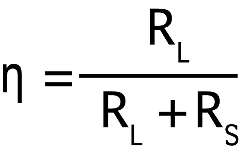
For DC circuits, efficiency is essentially the power dissipated at the load as a fraction of power dissipated at the source. Therefore, efficiency is calculated through the following equation shown in Fig 3.
Click image to enlarge
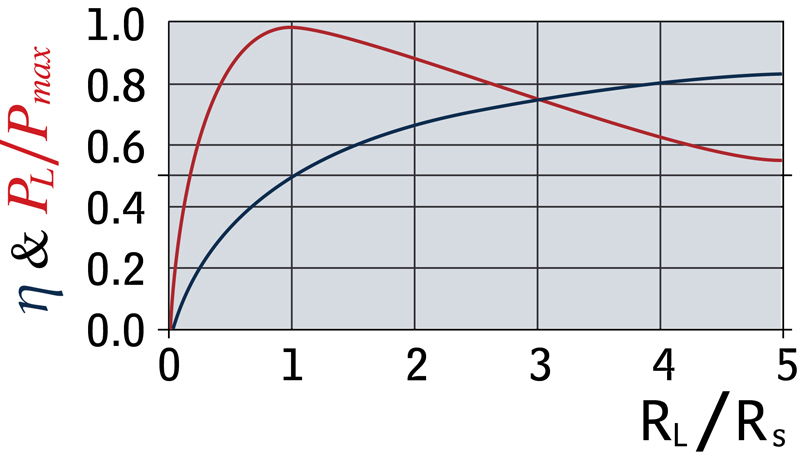
Figure 3. DC Circuit Efficiency
A plot of efficiency and power transfer ratio as a function of RL/RS is shown in Fig 3. It can be seen that maximum power transfer occurs when the source resistance and load resistance are equal. The power curve above shows that a maximum power transfer system has efficiency losses of 50%.
For AC circuits, it is the impedance that needs to be considered. If the impedance of the source is lower than the impedance of the load, the magnitude of power transfer is reduced, but the efficiency of the transfer is increased.
For maximum power transfer in AC circuits, the source impedance and load impedance must be complex conjugates — meaning the source resistance and load resistance must be the same, while the source reactance and load reactance must be equal in magnitude but opposite in phase. See Fig 4.
![]()
Click image to enlarge
Figure 4. AC Circuit Maximum Power Transfer
For most electronic circuit applications, the maximum power transfer is chosen over maximum efficiency. The power that is not transferred is dissipated as heat.
Impedance Matching
It’s clear that being able to match the load impedance is essential to the functionality of the circuit, especially for maximum power transfer. The simplest method of matching the load impedance is to use a transformer.
Transformers
A transformer is a highly efficient device (between 95-98.5%) used to transfer electrical energy from one circuit to another through electromagnetic induction (Fig 5). Transformers are made by wrapping two coils of wire (windings) around an iron/ferrite core. When an excitation voltage is applied to the primary winding, a magnetic field is developed in the core, which then induces a current in the secondary winding.
![]()
Click image to enlarge
Figure 5. Transformer Theory of Operation
The ratio of the primary voltage to the secondary/load voltage is the same as the ratio of primary winding’s number of turns to the secondary winding’s number of turns. This ratio will be called “n”. See Fig 6, primary to secondary voltage load.
![]()
Click image to enlarge
Figure 6. Transformer Primary to Secondary Voltage Load
The primary/source impedance and the secondary/load impedance are also related via “n”. This is often known as the “impedance ratio” of the transformer circuit (Fig 7). This shows that the load impedance can be quite simply controlled by selecting the correct transformer specifications for the chosen circuit, allowing for maximum power transfer.
![]()
Click image to enlarge
Figure 7. Transformer Impedance Ratio
Impedance Matching In Practice
Let’s look at two problem-solution examples to gain a better idea of how impedance matching works in the real world.
Problem 1
An audio amplifier is required to drive a load at maximum available power. The impedance of the amplifier is 300 ohms and the impedance of the load is 75 ohms. When connected directly, the signal transfer is poor.
Solution 1
The difference between the source impedance and the load impedance is causing the poor signal transfer. By using an impedance matching transformer, the load impedance can be matched properly to the source impedance.
The question then becomes: What transformer winding ratio is required to match the load impedance to the source impedance? The calculation in Fig 8 provides the answer: A 2:1 winding ratio is required.
![]()
Click image to enlarge
Figure 8. Calculating the Transformer Winding Ratio (Example 1)
Problem 2
For a different model audio amplifier, the 75 ohm load has been swapped out for a 12 ohm load. What is the new transformer winding ratio required for maximum power transfer in this circuit?
Solution 2
Fig 9 shows that a 5:1 winding ratio is required for this model audio amplifier’s circuit design.
![]()
Click image to enlarge
Figure 9. Calculating the Transformer Winding Ratio (Example 2)
Applications and Considerations
Impedance matching transformers can be used in any AC circuit, but are most frequently used for audio equipment, microphones, amplifiers, data networks/data systems, telephone grids, phone systems, and communication on airplanes — any application where power transfer must be maximized and distortion minimized.
While working out the impedance ratio of a circuit is simple, selecting a transformer in practice is a little more complex. Several factors must be taken into consideration, including:
Core Saturation — Magnetic materials (such as the core of a transformer) can only absorb up to a certain density of magnetic flux. When an electromagnetic device approaches magnetic flux saturation, it begins to behave in a highly nonlinear manner. The higher the signal level, the higher the transformer’s magnetic flux.
When the core is saturated, the primary signal cannot be faithfully reproduced in the secondary side of the circuit, which results in signal clipping where the peak values of the voltage and the current are dropped, as the required power output is greater than what the transformer can provide.
Core saturation can be avoided by choosing a larger transformer made from the same materials or using a core material that saturates at a greater magnetic flux density. Lots of time and money are being spent researching exotic new materials and configurations for this very purpose! The maximum power capability determines the minimum size of the transformer.
Frequency — Due to similar nonlinear effects, transformers only perform adequately over a limited range of frequencies. While the transformers for mains power operate at the low frequencies of 50 and 60Hz, transformers for signal transmission must operate over a wider range of frequencies: For example, the audio frequency range (20 Hz to 20kHz), or even higher for the radio frequency range.
Designing in a transformer into a circuit that is not adequate for the frequency range can cause signal and power losses, as well as overheating. Careful manufacturing techniques and specialized materials are required to construct transformers that operate well over a wide range of frequencies.
As a rule, circuit designers should always consult the transformer manufacturer before making a final decision on an impedance matching transformer; this will help ensure that the right choice is made for the application and it achieves optimal performance.
Conclusions
By matching load impedance, impedance matching transformers play a critical role in ensuring smooth operations in a wide range of circuits applications in various industries. Due to the fact that the ratio of impedance in the source and the load affect how much power can be transferred from the source to the load, circuit designers should double-check to be sure that the source impedance and the load impedance are equal in magnitude.
Triad Magnetics