Implementing a PWM controller
Creating a digitally-configured analog control #pwm #control #digital #microprocwessor #psd
Here we’ll look at how a rugged and flexible control can be rapidly implemented using an 8-bit microcontroller with analog blocks. For many custom power supplies, this provides an optimum combination of noise immunity, high performance, short development time, and digital flexibility.
Analog PWM control circuits
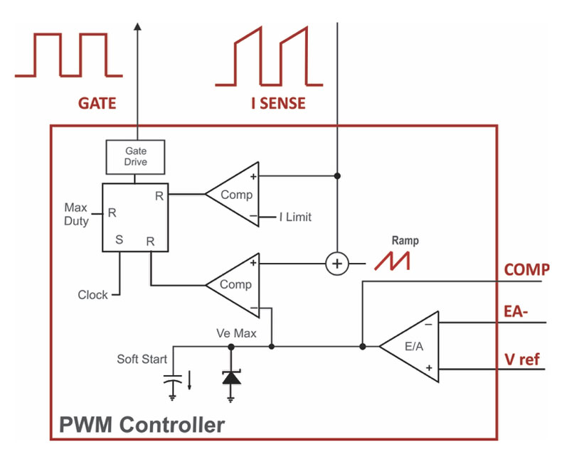
Figure 1 shows a traditional PWM controller, such as a well-tested 3842 design. The output voltage from a power supply is compared to a reference, amplified and compensated, and inserted into a comparator fed with either a saw-tooth ramp of a current-mode signal. Such controllers have been around for 30 years or more, and are rugged, reliable, multi-sourced, and thoroughly tested in the industry.
Click image to enlarge
Figure 1: Traditional Analog PWM Controller
Despite their age, these analog circuits maintain a strong presence in the industry.
Advantages are as follows:
1. Very good noise immunity. The control chip operates in a high-noise environment, but the ramp-reference approach and the op amp perform superbly with low cost parts.
2. High-speed prototype development and debug. Parts are well understood and documented, and all waveforms are available for probing and analysis.
3. Infinite resolution of the PWM output pulse with simple comparator.
4. Tight regulation using analog amplifier with reference at the input.
Disadvantages are:
1. No programmable flexibility through code changes. Component values or connections must be changed on the circuit board.
2. Poor tolerance on the main clock. This is generated with an analog ramp and reference, and is very prone to noise, jitter, and false early resets. Clock jitter shows up as random noise on the output that cannot be filtered.
3. Difficulty in adding current-mode compensating ramp. This must be done with external network and summed with the sensed current.
4. Too low a value on the current-sense headroom. Most ICs design assuming resistive sensing of current. At higher power levels, current transformers are used, and more signal is desirable.
Different levels of digital control
Digital control promises to fix all the issues of analog control, but it also creates a lot of issues in their place. We will discuss these in future articles. There are four major levels at which digital control can be implemented:
1. Full digital control. All analog inputs are processed with D-A converters, and compensation and duty cycle are set for each cycle by the microprocessor. A high performance controller is needed with fast math accelerators to meet high-bandwidth performance requirements. This is not ideal for lower power and lower cost systems, although most digital designers would tend to go this way and assume it works better. Code ruggedness is a severe issue if taking this approach.
2. Digital with analog PWM output comparator. Full digital compensation and input D-A processing as above, but output PWM pulse is generated with a PWM comparator. Research and experience has shown that a PWM comparator manages the fastest loop, and reduces the burden on the digital processing.
3. Digitally configurable analog blocks. Digital processor used to configure analog functions to rebuild an analog circuit. All the advantages of analog are retained with the added benefit of a reconfigurable system when it is needed. Digital monitoring is also included.
4. Digital monitoring with fixed analog blocks. This is basically an analog controller which is hard-wired for standard functionality.
Digitally-configured analog control
8-bit Microcontrollers are available from Microchip that allow a power supply designer to configure their own analog PWM controller. This offers a great opportunity to fix many of the bugs of old analog control chips, while also incorporating the flexibility of digital functions for complex designs. For many applications, this provides the best of both worlds.
Many analog designers have a good sense of what they would want in a new analog part, but IC manufacturers rarely listen to power designers and give them what they need. With the new microchip part, analog designers can easily configure their ideal control chip. This can lead to maximum productivity in developing power supply designs.
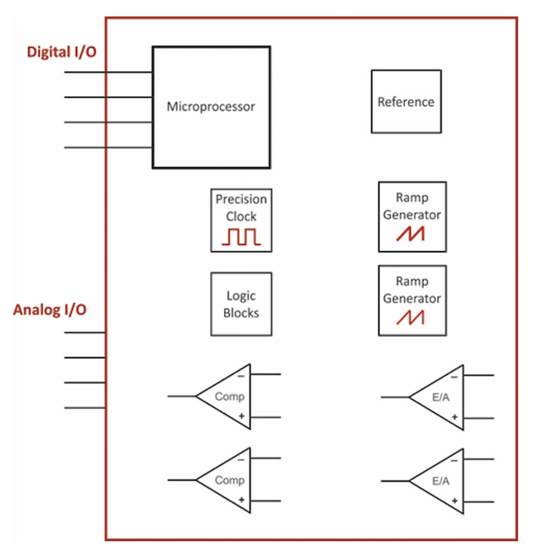
The controller is shown in Figure 2. A microprocessor is used to set the connections between multiple analog peripherals. All of these run independently of the microprocessor core, and are hence referred to as core-independent peripherals. (CIPs). Since they are full analog, they have none of the phase delay problems inherent to full digital control, and maximum bandwidth can be obtained from the system.
Click image to enlarge
Figure 2: Digital Controller with Configurable Analog Building Blocks
Several of the problems of analog controllers are completely solved with this approach.
1. A precision clock. The frequency is set with 0.25% accuracy, and is not subject to jitter. This allows smooth operation as the converter enters regulation, something that is very rarely experienced with normal analog control. Having a precise clock is a great help in tracking down many of the noise-related instability effects of PWM control chips.
2. Creation and summation of the current-mode compensation ramp. This can actually be subtracted from the error amplifier voltage, rather than added to the current signal, allowing much more straightforward design and debug.
3. Ability to set maximum duty cycle with tight tolerance. Converters can be run at larger duty cycles since the timing is now so precise.
4. The headroom of the current sense input can be set as high as 5 V. This allows for high-noise and high-power applications where current transformers should be use to provide good noise immunity.
Digital implementation barriers
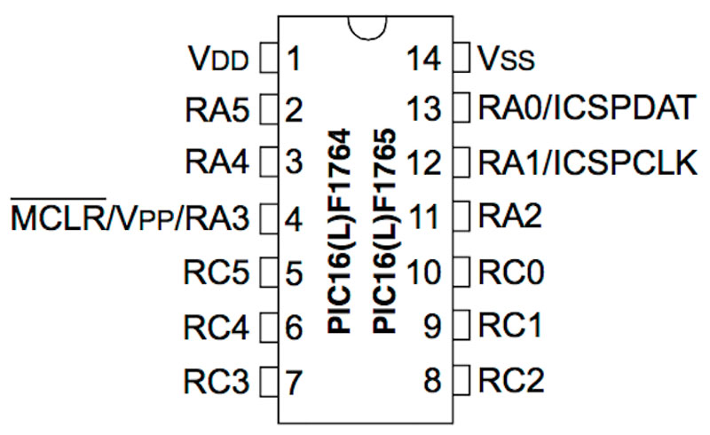
Many designers would like to implement some form of digital control, but find the process intimidating. When you look at the 564-page datasheet for this part, the pinout diagram gives no indication that this can be such a powerful and versatile analog controller. The pins are cryptically labeled when viewed by an analog engineer (see Figure 3). (Looking at the labeling, and examining the exhaustive datasheet completely conceals the usefulness of the chip. We discovered the part by chance when a Microchip engineer showed it to us at one of our design seminars.)
Click image to enlarge
Figure 3: Datasheet Pinout for Controller
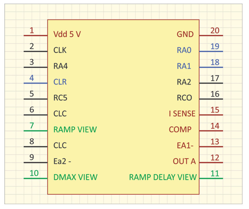
Once the proper program has been loaded into the processor, however, the pins can be relabeled in much more familiar ways. The red pins in Figure 4 correspond to the familiar 3842 controller. However, the performance greatly exceeds that of the 3842 with a precision noise-immune clock, and implementation of higher voltage thresholds, and a fully-controllable compensation ramp.
Click image to enlarge
Figure 4: Revised Pinout Ready for Layout
Joining the streams
A new option now exists for designers to combine both analog and digital control into a low-cost part. For the first time in our industry, it is possible to easily build a custom PWM controller with analog blocks. At the same time, many of the nagging issues of popular analog ASICs are solved with the new implementation. This provides the designer with great freedom in setting up a rugged and flexible controller to work properly with a power system. A comprehensive application note can be downloaded from [1] to learn more about using this new part.
References
1. Microchip application note: ridleyengineering.com/download-microchip-appnote.html