Implementing an Overcurrent Protection Device
Overcurrent protection is protection against excessive currents or current beyond the acceptable current rating of the device. To protect downstream loads, the point of overcurrent protection should occur at the FET switch.
An overcurrent protection device can be implemented using a GreenPAKSLG46116V chip. The SLG46116 includes a P-FET Power Switch designed for load switching applications. The P-FET Power Switch can be controlled internally via the ON digital input of the P-FET Power Switch component in GreenPAK Designer, allowing the user to generate integrated mixed-signal control circuits.
The P-FET Power Switch contains a 28.5mΩ RDSON, 1.25 A P-channel MOSFET with fixed slew rate control. The device has a built-in soft-start, which controls the output rise time. This minimizes inrush current when the switch is enabled.
For this implementation, the protected circuit is connected to the voltage supply via the SLG46116V chip P-FET.When the current in the protection circuit reaches the preset maximum current rating value, the GreenPAK device can almost instantly turn off the P-FET power switch and stop the flow of “overcurrent”.
Circuit Design and Analysis
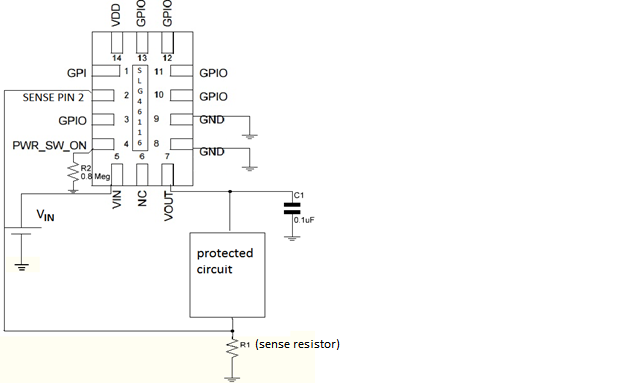
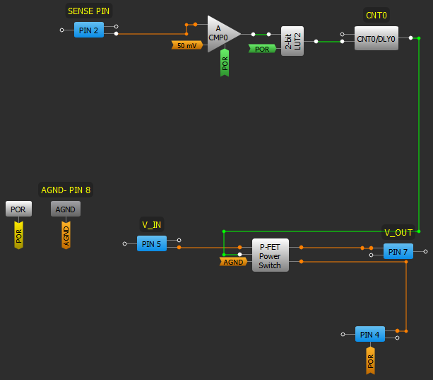
An overcurrent protection application circuit with the block diagram of the SLG46116V chip is shown in Figure 1, and the internal design of the chip is shown in Figure 2.
As seen in Figure 2, besides the P-FET switch, the design requires additional components, one ACMP, one 2-bit LUT and one DLY.
To use the ACMP in a GreenPAK design, the power up signal (PWR UP) needs to be active (HIGH). Before the power-up signal POR, the ACMP is powered down. Its output is low, the output of LUT2 is low, and the ON signal of P-FET is inactive. After the power-up signal POR, if the current does not exceed the rated limit, then the ON signal will be active (high) and the switch is closed providing the power supply to the connected circuit.
Click image to enlarge
Figure 2. Overcurrent Protection Circuit GPAK3: SLG46116V Design
The overcurrent limit threshold can be programmed/designed by selection of external resistor R1 in Figure 1, which is connected between the protected circuit and GND, and by selection of the IN- Vref value of ACMP, which has 24 internal reference sources (50 mV – 1200 mV) and VDD/3, VDD/4, PIN 4.
The current limit can be calculated as the IN- Vref divided by the external resistor R1. In this design example, IN- is 50mV and R1 =0.2 Ω, thus the current limit is equal to 250 mA.
If the current exceeds 250mA the output of ACMP is low, the ON signal is low (inactive) and the P-FET switch is open, thus the overcurrent flow is interrupted.
Once the overcurrent problem has been interrupted, the delay time of DLY0 (adjustable) will define the recovery time after which the P-FET will switch into the “ON” position and the protected circuit will resume being powered. This can cause a continuous cycle of switching on and off the PFET if the overcurrent is not resolved.
The domain for VIN: 1.5 V to 5.0 V. When ON is configured to be controlled internally, PWR_SW_ON (PIN 4) is configured as Push-Pull output.
When VIN is not used in the same voltage domain as VDD, using a large pull-down resistor on PWR_SW_ON (PIN 4) is recommended to prevent current from flowing through the P-FET Power Switch while the device is not powered. Also, to prevent glitches at the output, it is recommended to connect at least 0.1 mF capacitor from VOUT pin to the GND.
Conclusion
An overcurrent protection device can be easily implemented using a GreenPAK 3 that includes a P-FET Power Switch. It has low power consumption and few external components.
Tijana Uzelac received her Master’s Degree in Electrical Engineer in 2005 from University of Belgrade, studying at School of Electrical Engineering, Physical Electronics Department. In 2016, she received the Interdisciplinary Renewable Energy Certificate from Santa Clara University, ECE Dept. She began her work for Silego Technology Inc. in 2015.