Improve power conversion testing with these probing tips

Accurately evaluate and measure very small performance increases
Today’s power supply designers and test engineers are generally seeking to find very small incremental improvements that will increase power conversion efficiency, or reduce losses in the design. This requires the ability to accurately evaluate and measure very small performance increases.
Sources of loss may be found in nearly every sub-section of a power converter, with key areas of interest often being the switching semiconductors, magnetics, and rectifiers. Performance improvements in the low-digit percent values and fractions of a percent can be meaningful. But to accurately evaluate and measure such small performance increases, highly accurate measurements are critical.
Most oscilloscopes ship with 10X attenuation passive probes because this type of probe is a good for making measurements across a broad range of applications. These probes are typically rated from DC to 500 MHz and are generally capable of measuring up to a few hundred volts. While it’s certainly possible to use general-purpose probes for power measurements, they are unlikely to deliver the level of accuracy needed to drive performance improvements compared to probes designed specifically for power applications.
Signal sensitivity
Let’s look at an example of where a general-purpose probe falls short. A common challenge in power supply design and measurement is to separate noise from ripple voltage. In this example, we’re attempting to probe a 3.3 V power supply using a general-purpose 10X probe. The problem is that the 10X probe doesn’t provide enough sensitivity to trigger on period noise present in the waveform. These probes are a good choice for many general electronics measurements since they increase the voltage range of the scope and offer relatively high bandwidth.
However, for measuring low level signals in the tens of millivolts, a 1:1 (1X) probe may be a better choice, because it does not attenuate the signal as much and does not push the signal down into the noise floor of the scope. Unfortunately, the sensitivity benefit is offset by limited bandwidth, usually around 15 MHz. If this bandwidth is insufficient for your measurement, a passive 2X probe may be a better alternative
In this application, a 2X probe proved to be the right choice. Consider the waveforms in Figure 1. The yellow trace is a 10X probe adjusted to the lowest vertical setting of 10 mV per division and the blue waveform is a 2X probe. The 2X probe can be adjusted down to its lowest vertical setting of 2 mV per division. Since the output of the power supply produces a signal with 3 mV of ripple, it’s clear why a probe with 10X attenuation is not well-suited for this measurement.
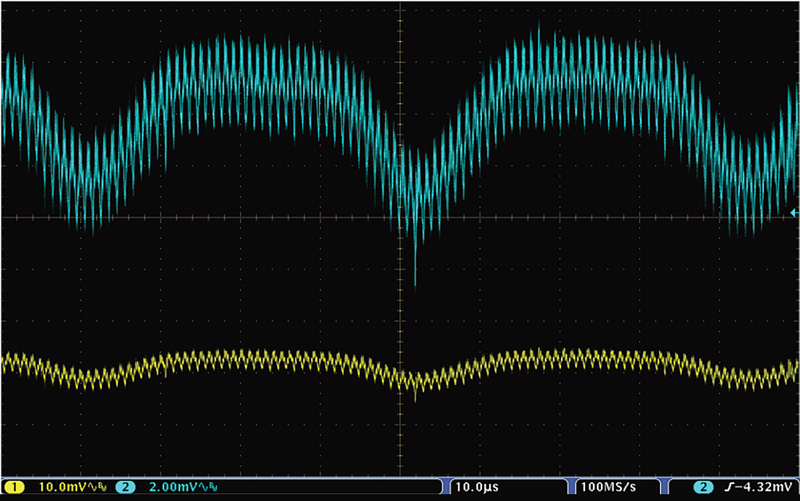
Click image to enlarge
Figure 1. A 3.3 V supply measured with a 2X probe (blue trace) and a 10X probe (yellow trace).
Differential measurements
A ripple measurement such as that just discussed is one application where a single-ended (ground referenced) probe can be used effectively and safely in power supply design and debug. But many measurements on power-conversion need to be made in a floating environment, where reference to earth ground is not available.
Figure 2 identifies several common power conversion measurements that are not tied to ground and require differential measurement techniques:
1. Drain to Source Voltage (VDS) on a MOSFET
2. Diode voltage on a freewheeling diode
3. Inductor and transformer voltages
4. Voltage drop across ungrounded resistors
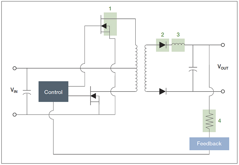
Click image to enlarge
Figure 2. Some of the differential measurement points on a push/pull power converter.
There are several ways to perform differential measurements, including:
· Use two single-ended probes and calculate the difference voltage
· Use an oscilloscope with specially-designed floating inputs
· Select a differential probe best matched to the measurement
Two single-ended probes
A common technique is to use two single-ended probes with each probe’s ground lead tied to earth ground and the tips on either side of the component under test, as shown in Figure 3. The oscilloscope is then set to show the difference between Channel 1 and Channel 2. This is sometimes called “A-B” and it displays the difference voltage between the channels using math in the scope. This technique is sometimes used by engineers when they need to make a differential measurement but don’t have the appropriate test equipment available.
Click image to enlarge
Figure 3. Making a quasi-differential measurement with two single-ended probes.
There are several problems with this approach. This method will provide good measurement results only when the probes and the oscilloscope channels are very well matched (gain, offset, delay, and frequency response). This method also doesn’t provide very good common mode rejection (nulling out any AC or DC portion of the signal that is common to both inputs). And, if the two signals are not properly scaled, you run the risk of overdriving the oscilloscope inputs and getting erroneous measurements.
Floating inputs
Using a “floating” oscilloscope is another alternative. Each of the input channels of these oscilloscopes is electrically isolated from chassis ground, and then the oscilloscope is powered by its battery. The parasitic capacitance from the oscilloscope chassis to earth ground is also very low. Together, these isolation characteristics of a floating oscilloscope enable differential measurements with an insulated passive probe. These instruments are convenient, easy to use, and give good results. However, differential voltage probes have lower capacitance and are highly balanced.
Matched differential probe
For the best measurement accuracy, a differential probe with specifications matched to the measurement task is usually the best choice. Differential probes are active devices. They include a purpose-designed differential amplifier in the probe tip that measures only the voltage across the two test points, regardless of the potential between either test point and ground – greatly simplifying the probing task and eliminating some possible sources of error. And since they measure only the differential voltage, they also can ignore – and null out – common mode AC swings or DC offset voltages that may be present.
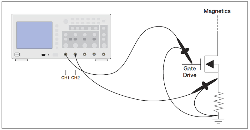
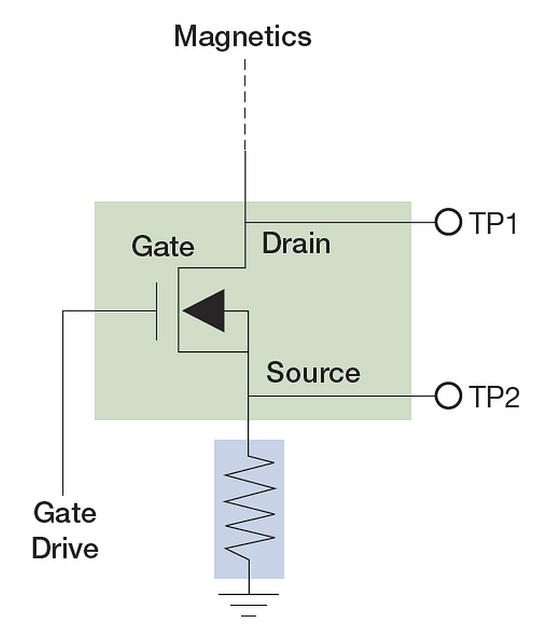
Because measurements in different parts of the device under test (DUT) may have very different requirements, it’s important to choose probes carefully. In the example shown in Figure 4, the task at hand is measuring Turn-on Loss, Turn-off Loss, and conduction loss in the MOSFET switching component of a power supply under test. Figure 4 shows a simplified diagram of the MOSFET with measurement points, TP1 and TP2.
Click image to enlarge
Figure 4. Simplified diagram of a MOSFET with test points.
The device under test is a “universal” power supply, designed to be powered from AC line (or “mains”) voltage in countries all over the world. This fact alone brings several implications for the engineer’s test requirements – and test equipment:
· Input voltage ratings for this type of device typically range from 80 VAC to 250 VAC or wider. To characterize performance across a variety of input-voltage conditions worldwide, you need to perform not just one measurement, but a series of measurements at several input voltage levels. This applies to each performance parameter to be tested. Switching characteristics (and therefore losses) can be expected to be different at each of these input voltage levels, and may not vary in a linear fashion. This increases not only the total number of measurements to be taken, but also the need for repeatability from measurement to measurement.
· With input supply voltage levels as high as 250 VAC, the voltage levels between Drain and Source in the switching MOSFET can be expected to reach 354 volts or higher. The probing solution needs to be versatile enough to measure these voltage levels along with much lower levels for some tests.
The power supply under test has a switching rate of 250 kHz. Using the common” 5X” rule of thumb for measurement bandwidth, this equates to a measurement bandwidth requirement of 1.25 MHz. But this is a simplistic view of real-world signal speeds since actual rise-times of the switching components can be expected to exceed this by an order of magnitude. The same is possible for spikes, transients and other noise that may need to be investigated. If you are measuring signals with rise times in the 10s of nanoseconds, the probe should have a rise time spec in the nanoseconds. For accurate measurements in this example application, the bandwidth of the measurement system should be on the order of 350 MHz or higher.
Summary
Selecting the best probe is highly application-dependent and therefore it is important to understand measurement requirements of your application and make sure yours probes are well-suited to the job. Differential probes are a clear choice for many power-electronics measurements, especially those that are not ground-referenced. For grounded measurements, single-ended probes are a good option but take care not to use 10X probes and over-attenuate small signals. For low-voltage signals, such as ripple, a 1X or 2X probe may be a better choice.