Improving BLDC motors with sensor-less control
There are many places inside the latest vehicles where advanced systems of this type can be found
The implementation of 3-phase brush-less direct current (BLDC) motors is becoming increasingly widespread in contemporary automobile designs. There are now a multitude of different places inside the latest vehicles (from luxury right through to economy models) where they can be found - having proved themselves to deliver greater reliability (as mechanical wear and tear is avoided) and power efficiencies than conventional mechanically-commutated motors. The following article will discuss the advantages that sensor-less control of such motors presents in terms of the system’s overall cost and its performance.
With accumulative pressure being placed onto the automotive sector to raise fuel efficiency levels and reduce carbon emissions, BLDC motors are now being employed in electrical auxiliary units (such as water/oil/fuel pumps, the compressors in active suspension systems and the blowers of climate control systems) with increasing frequency. The traditional motor control systems (which employ rotor position sensors to ensure that synchronization is maintained) are now starting to become outdated. Instead sophisticated sensor-less implementations offer a more effective means by which to control and regulate BLDC motor systems.
Important factors affecting motor control design in automobiles
When putting the power IC technology in place for a modern motor control system, there are several key considerations that engineers need to be made aware of. These are as follows:
1. Available board space is (of course) going to be limited
2. The total system cost needs to be kept in check
3. The operational temperature range supported needs to be broad due to implementation in a challenging automotive environment
4. A wide voltage range will need to be supported too
5. Protection mechanisms will need to be in place to deal with voltage surges and spikes, as well as the possibility of load dump conditions arising
The space and budgetary constraints mandate the specification of power ICs with a high degree of integration. Through this it will be possible to ensure that only a relatively small amount of board real estate needs to be taken up and the number of external components required can be minimized (thereby keeping the bill-of-materials costs low).
The desire to reduce costs, save space and improve reliability has made sensor-less control more and more attractive. This approach eliminates the need for electromechanical components, which are generally bulky, expensive and somewhat prone to failure.
Sensor-less control is accomplished by being able to determine the position of the rotor via the electro-motive force (BEMF) voltages observed within the system. As only 2 of the 3 phases are excited at any time and the other one is left inactive, the BEMF of the inactive inductance can be used to obtain data on the rotor position.
The motor system’s operation can be subdivided into three distinct stages:
1) Rotor position detection at standstill
2) Starting the motor with rotor position detection from standstill by measuring the inductance values on the coils
3) Running the motor with rotor position being determined through measurement of the inductance values on the coils
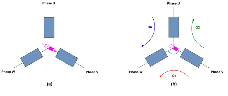
To begin with, we shall consider detection of the rotor position while at standstill. Figure. 1a shows the rotor position in relation to the stator with the 3 inductances V, U and W all denoted. The retroactive effect of the rotor’s magnetic vector means that the inductance of the stator coils depends on the rotor position. Figure. 1b details the motor start with rotor position detection from standstill. From the inductances, via a suitable test method, the data necessary for determining the rotor position can be accurately acquired.
Click image to enlarge
Figure 1: The diagrams shown here describe (a) the magnetic vector of the rotor in respect to the stator coil (b) the energizing process to start the motor
Since various parameters can be very temperature dependent (e.g. viscosity of oil), for certain applications (such as oil pumps) motor start will occur under load conditions that have not been determined. If the rotor is to move in the indicated direction of rotation (as described Figure 1b), then a torque producing current Q1 will need to be applied. Regardless of its design, the motor will start in block mode, with measurement via inductance U. Through pulse-width modulation, 2 alternating currents are introduced to UV and UW.
These are referred to as Q2 and Q6 - with even numbered modulation intervals for Q6 and odd modulation intervals for Q2. As UV and UW are influenced by the rotor position, analysis of Q2 and Q6 enables the rotor position to be determined without Hall Effect sensors being required. After the rotor has completing a 60° interval, the system commutates and a new cycle is initiated. The speed is given by of time period needed for each 60° interval to be completed.
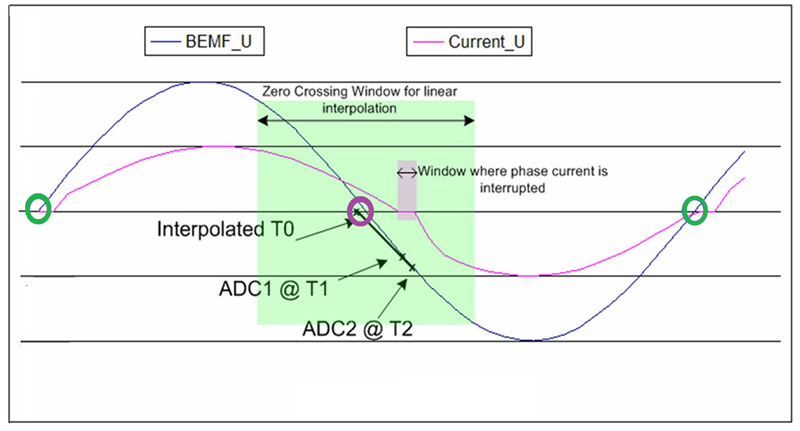
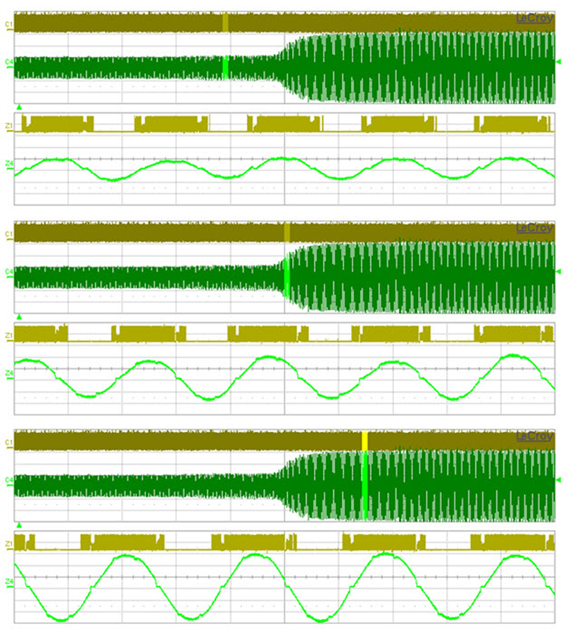
Through the BEMF and the commutation signal the speed can be measured, and it is possible to ensure that it maintains a high enough level to permit sensor-less control (as the BEMF is proportional to the rotor speed, so the this needs to be high enough for sufficient BEMF to be generated). Next, the third stage of the process needs to be examined. Here the motor will be running, regardless of the current profile used with rotor position detection via BEMF. Once the motor has accelerated sufficiently, BEMF detection of the rotor position can be used (see Figure 2).
Click image to enlarge
Figure. 2: Waveform for third phase of motor operation
If the motor has sinusoidal commutation, then the BEMF and motor current will also be have a sinusoidal form. Thus, depending on the load current/BEMF, it is possible that either phase lead or phase lag might be observed. From the feedback signals of the motor, the zero crossing of the current can be detected - this will basically give the moment at which the inductor coil has been fully de-energized. The phase current is then maintained at this point for a brief length of time, so that BEMF values for the coils covering 2 phases can be taken. The zero crossings of the BEMF can then be calculated through simple interpolation.
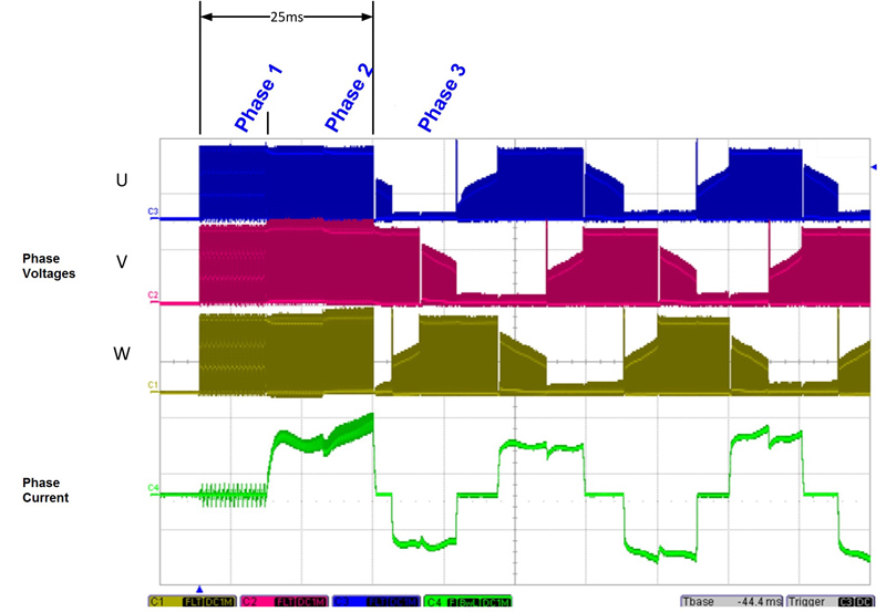
In Figure 3 a practical example is described of a sinusoidal commutated motor starting up under load conditions. Both the phase current and phase voltage are given for 3 different loads. The BEMF measurement can be seen. At the rise of the motor current, a variable load is observed.
Click image to enlarge
Figure. 3: Phase current & phase voltage when starting motor
The BEMF data accessed by the system enables the phase currents be controlled, in order for the BEMF and phase current to remain synchronized with one another. By doing this, the motor can be run with optimal energy efficiency. Figure 4 shows the activation and subsequent ramp up of a BLDC motor under load. Since phase 2 is self-adaptive though the motor start-up process, once started, it maintains reliable operation under all load conditions.
Click image to enlarge
Figure. 4: Schematic showing phases 1 to 3 of a block commutated motor
Utilising proprietary TruSense technology, Melexis has introduced a series of AEC-Q100 qualified, 16-bit, flash-based driver ICs that are aimed at BLDC motor control in automotive applications. The series is made of its MLX81205, MLX81207, MLX81210 and MLX81215 devices. Through BEMF measurements, TruSense can deliver highl precision rotor position data across a very wide dynamic range and under extreme changes loads. These devices can cope with ambient temperatures up to 150®C, along with an operating voltage range covering 5V to 18V being supported.
The MLX81205/07/10/15 series presents a consistent platform with software compatibility between all of its constituent devices. Individual driver ICs support different interface technologies and memory sizes. Sensor-less control of BLDC motors via determining of the rotor position is straightforward to accomplish using one of these devices. The central processing unit of a MLX81205/07/10/15 driver IC can gain direct access to the power transistors of the output stage. This offers considerable flexibility with regard to setting of different switching profiles.
Sensor-less controlling of BLDC motors has shown itself to be highly cost effective, as it leads to a marked decrease in component count. The advent of next generation, highly integrated driver IC solutions will encourage the proliferation of this method of motor control.