Proper thermal design is necessary to ensure quality and reliability of SSL products
Many LED failures are temperature related since an LED’s performance and projected lifetime correlate tightly to thermal management and the resulting junction temperature of the LED semiconductor chip. Elevated junction temperatures cause a reduction in light output and accelerated LED lifetime degradation. Proper thermal management of an LED luminaire is vital for performance (see Figure 1). Measuring and validating thermal design assumptions is necessary to ensure quality and reliability of SSL products.
Click image to enlarge
Figure 1: Proper thermal management of an LED luminaire is vital for performance
Some performance characteristics experience a recoverable change, such as light output, color and voltage, while others, such as lifetime, can experience a non-recoverable degradation due to high operating temperatures. However, exceeding the maximum operating temperature specification, which is typically a 150 °C junction temperature, can cause damage to LEDs, so care must be taken to operate LEDs below this limit.
Light output issues
Important performance characteristics and implications of improper thermal management include light output, as elevated junction temperatures cause recoverable light output reduction. As the junction temperature increases, the light output of the LED decreases, but recovers when the LED cools. Also, with increasing junction temperatures, the color of all LEDs shifts.
Voltage
Forward voltage decreases as the junction temperature of an LED increases. It is important to understand the full operating conditions for an LED system so the driver can accommodate the potential range of drive voltages over the operating temperature of the system.
Reliability
The reliability of any LED is a direct function of junction temperature—the higher the junction temperature, the shorter the lifetime of the LED. Data from an IES LM-80-08 report can be used to predict the lumen maintenance of an LED under various temperatures and drive current operating environments. A TM-21 calculator from the Environmental Protection Agency (EPA) can be used with the LM-80 data to predict lumen degradation and expected lifetime under specific operating conditions.
Heat Generation
LEDs generate visible light when current passes across the junction of the semiconductor chip. However, LEDs are not 100 percent efficient; much of the power running through an LED is output as heat, which thus needs to be dissipated. For example, Cree royal blue XLamp LEDs are over 50% efficient and white XLamp LEDs are over 40% efficient. That means, under ideal operating conditions, approximately 50% to 60% of the input power is output as heat, while the rest of the input power is converted to light. The harder an LED is driven, the less efficient it is, so to be conservative, assume LEDs convert 25% of the input power to light and output 75% of the input power as heat when designing thermal management systems.
Heat Transfer
There are three basic modes of heat transfer: conduction, convection and radiation. Each plays a role in LED performance and final system design, and must be understood for proper thermal management.
Conduction:Conduction is the transfer of heat through a solid material by direct contact. This is the first mode of heat transfer to get thermal power from the LED junction to the heat sink. Metals are typically the best conductors of heat.
Convection:Convection is the transfer of heat through the movement of fluids and gases. In LED systems, this is typically the transfer of heat from the heat sink to the ambient air. There are two sub-categories of convection: natural and forced. Natural convection occurs with no artificial source of field movement and is due to the buoyancy forces induced by thermal gradients between the fluid and solid. Forced convection occurs when an external instrument such as a fan, pump or other device is used to artificially move the fluid or gas. In LED cooling systems, convection is the main mode of heat transfer to remove the generated heat from the LED system and heat sink.
Radiation:The transfer of thermal energy through an electromagnetic field is the third component of heat transfer, radiation. The magnitude of radiation heat transfer is based on the emissivity of the material, which is the ratio of how closely the surface approximates a blackbody and the temperature gradient of the system surfaces relative to the ambient air. In an LED system, radiation typically has a very small effect on the net system heat transfer since the surface areas are typically fairly small and surface temperatures are relatively low, to keep the LED junction temperatures below the maximum rated temperature of 150°C.
Thermal Stack
For purposes of thermal analysis, an LED system typically consists of a multi-component assembly, called a thermal stack, in which all components contribute in varying degrees to the total system thermal performance. In a typical system, the LED is soldered to a PCB, either metal core or FR4, which is then usually attached to a heat sink. It is critical to maximize heat transfer between the heat sink and PCB, so a good thermal interface material (TIM) is needed to fill any air voids. The best method to enhance the thermal path and minimize the system thermal resistance is to minimize the number of materials in the thermal stack and use the most thermally conductive materials available.
The heat sink is the most influential part of the thermal stack, and is needed to first conduct heat away from the LEDs and then to convect and radiate heat to the ambient air. Thus, the first task of the heat sink necessitates that the heat sink be fabricated from a high thermal conductivity material to conduct heat away. The second task requires that the heat sink have a large surface area to convect heat to ambient and also have high emissivity so it can radiate heat away.
When the thermal load of an LED system is too high to be properly dissipated by passive means, active cooling may be the only solution. There are many types of actively cooled systems, from fans to liquid cooling to heat pipes to other exotic methods. The effectiveness, reliability, noise, cost, added power (and thus lower system efficiency) and maintenance of these devices need to be weighed against the benefits of an actively cooled system. Very few active cooling devices can equal the long LED lifetimes of many thousands to hundreds of thousands of hours, so care must be taken to not compromise system lifetime with inept active cooling solutions. An LED system is only as good as its weakest link, and active cooling can be this link without careful selection.
Thermal Measurement
Accurate temperature measurements are required to appropriately design a thermal system and to evaluate and assess an existing design. Whether for a final design or a prototype, the measurement process is the same and requires due diligence to make sure realistic and accurate measurements are made. LED reliability is a major advantage compared to traditional light sources, so proper and realistic measurement procedures should be used so this benefit is not jeopardized.
When performing thermal measurements, it is critical to set up the test subject as close as possible to the real-life, worst-case scenario to which the system may be subjected. Ensure that the measurement setup accounts for similar airflow, material properties, orientation, ambient conditions and any additional heat sources such as power supplies or contributory heat loads. This ensures that the temperatures measured correspond to real-world, worst-case scenarios and could identify potential problems that best-case scenarios may miss.
Another factor to note is the time required for the system to thermally stabilize. Depending on the size of the heat load and the mass and effectiveness of the heat sink, some systems take only a few minutes to stabilize while others take hours. It is best to monitor the thermal stability and wait one hour at the very least for each thermal measurement. It is also recommended to monitor the ambient temperature and look exclusively at the difference between the measurement point and ambient temperature, as any change in ambient will be reflected in the measured data.
Thermal Simulations
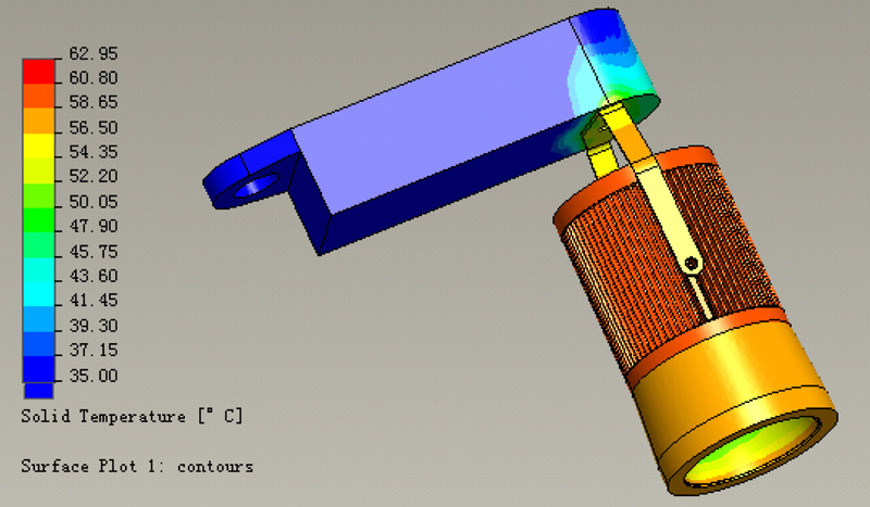
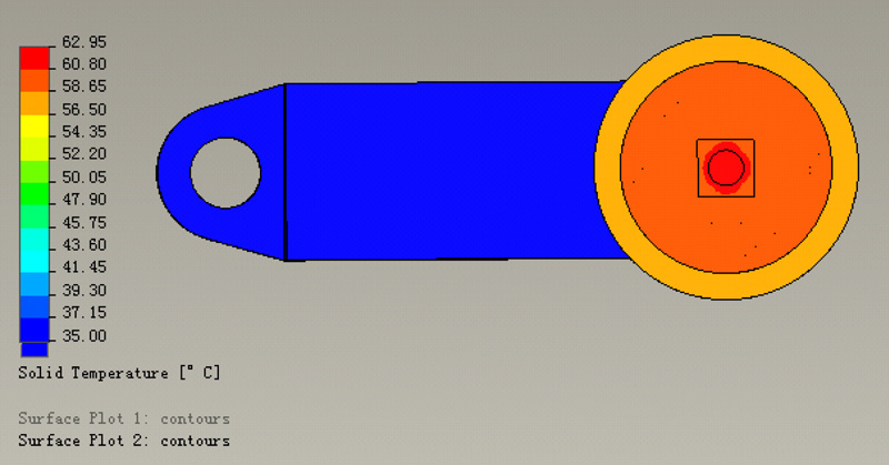
For early design validation, before investing in expensive prototyping and multiple design revisions, it is highly recommended to perform thermal simulations. Cree® Services offers thermal simulation through its Thermal, Electrical, Mechanical, Photometric and Optical (TEMPO) service options. Thermal simulations can show problematic areas and hot spots within a design and can allow for iterative design adjustments to address problems and optimize the system (see Figures 2a and 2b). Computational fluid dynamics (CFD) analysis further enhances thermal simulations by solving for conduction, convection, whether natural or forced, and radiation to fully evaluate the total system design and the effect of the fluid flow around the system.
Click image to enlarge
Click image to enlarge
Figures 2a and 2b: Thermal simulations can show problematic areas and hot spots within a design
Simulations are good for quick and inexpensive design adjustments and give a good visual representation of spreading, potential bottlenecks, and thus possible areas of improvement. After simulating a system and optimizing a design, building a final prototype to accurately measure its performance is always recommended. However, thermal simulations can be used to minimize the iterative steps of seemingly infinite prototyping by proactively reducing the number of options and focusing the design work instead of investing in prototypes, testing and repeating.