Incorporating Baseplate Cooled Converter Modules
When it comes to designing rugged equipment, the best way to make them reliable is to seal them from any external environmental conditions completely
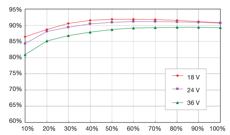
Figure 1: An example of the variation in efficiency with input voltage and load
When designing rugged equipment designed for outdoor use, sealing them from external environmental conditions is a prudent step, but it does introduce some design challenges, one of which is how to provide the power supply capability, particularly when relatively high levels of power are required. Most high-power supplies use forced air cooling to dissipate the heat generated, an approach that is not practical in a completely sealed unit. As a result, the use of baseplate cooled power converter modules – also called 'bricks', where they are mounted against a cold wall or unit casing and use conduction-cooling have become popular.
Designed as a component-level power module rather than a drop-in solution , bricks provide manufacturers of outdoor equipment and systems a low-risk approach to development that speeds time to market through the use of a range of proven, reliable and readily available power modules which can be utilized to create a bespoke power solution for the end application.
Products are available for both AC and DC input applications. AC input products can be either complete AC-DC solutions or PFC modules used to drive high input voltage DC-DC bricks. With a few exceptions, AC input products require the addition of external high voltage electrolytic capacitors. DC input products cover a wide range of nominal battery voltages, vehicle supplies and higher voltage applications, to around 450VDC, to cater for PFC modules or rectified mains voltages, high voltage battery solutions and renewable energy applications.
A set of industry-standard sizes have evolved, termed quarter bricks, half bricks and full bricks, power ratings up to 700 Watt can be found in an industry-standard 2:1 input full brick package. Achieving a wider input range of 4:1, 8:1 or even12:1 to standardize system design, covering a broad range of potential nominal input voltages, reduces the power density of the brick.
The design of baseplate cooled converters requires some additional design-in considerations, particularly for thermal management and electro-magnetic compatibility (EMC).
Thermal management
All power dissipating components within the brick are thermally bonded to the baseplate including power transistors, rectifiers, transformers and inductors. Thermal management of the module baseplate is crucial and it’s temperature needs to be maintained below the maximum operating limit at the worst-case condition demanded by the end-application. The cooling scheme's thermal resistance characteristics must be matched to the power required by the load or end equipment and the efficiency of the module, which determines the power dissipated in the brick converter, and the maximum temperature at which the equipment is expected to operate.
The module's operating efficiency specification under worst-case load conditions determines how much power is dissipated. This needs to involve a careful analysis of the module's efficiency across all likely input voltage ranges and the actual load conditions rather than purely calculating this from the module's stated headline efficiency. See Figure 1. The graph illustrates how a module's efficiency varies with input voltage and load.
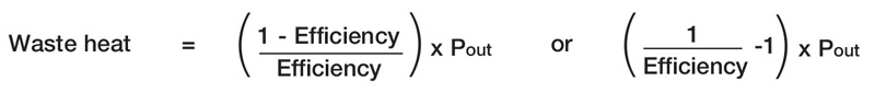
The calculation to determine the amount of power to be dissipated is shown below in Figure 2.
Click image to enlarge
Figure 2: Calculation of waste power to be dissipated as heat
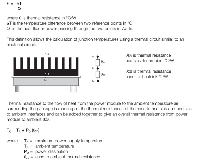
Having determined the waste heat/power, the simple model below determines the thermal resistance required for operation, with ∆T defined as the difference between the maximum operating temperature of the equipment and the maximum baseplate temperature of the power brick. The thermal resistance from the case to the heatsink is typically 0.1 ⁰C/W when using a thermal pad or thermal grease.
Click image to enlarge
Figure 3: Power Brick and Heatsink Thermal Model
In convection cooled applications, the physical size of the heatsink is far greater than a comparable solution using forced air or liquid cooling. If more than one baseplate cooled module is mounted on a common heatsink, cold wall or external casing the overall thermal resistance required determined by the sum of the dissipated power from all the bricks operating under worst-case conditions.
Electro-magnetic compatibility
Another critical aspect of baseplate cooled converter power system design is EMC, including protection against spikes and surges as well as the control of electrical noise emissions. The susceptibility requirements for the end-application define the extent and complexity of surge and spike suppression required, from simple passive components through to transient Voltage Suppressors (TVSs), Gas Discharge Tubes (GDTs) or even active clamp designs required in some vehicle and rail applications. Application specific EMC modules are available for defense & rail applications to provide low risk proven solutions in these demanding applications. The power module based power solution also requires suitable fusing or circuit breaker protection to be included for safety purposes and typically some local capacitance to reduce source impedance.
The power module datasheet and application notes specify the values of components required. However, it is up to the power system design engineer to implement them, following good design practices for any creepage and clearance requirements, and minimizing parasitic inductance for EMC compliance.
Click image to enlarge
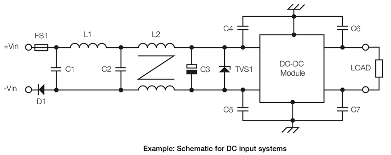
Figure 4: Schematic for DC input systems
With reference to Figure 4 the fuse, FS1, provides short-circuit input failure protection. Reverse polarity protection is provided by diode D1. L1, C1, and C2 are connected in a pi filter arrangement to reduce differential noise caused by rapid changes in current within the power switching stage. A common mode filter is formed by L2, C4, and C5 to mitigate noise generated by rapid changes in voltage in the power converter. Capacitor C3 presents a low impedance source for the power converter switching current demand and TVS1 is s a bi-directional transient surge suppressor to protect against spikes and surges. C6 and C7 reduce common-mode noise on the output although an additional differential filter might be required on the output for applications that stipulate a low noise power source.
When designing the power system layout, it is prudent to place the decoupling capacitors C4, C5, C6, and C7 as close as possible to the connection pins and the chassis connection to the baseplate in order to keep the loop short. TVS1, the transient voltage suppressor and the electrolytic capacitor C3 across the input should be kept as close to the input pins as possible. PCB tracks beneath the power module should be avoided.
If using a PFC module in front of the converter, a high-voltage electrolytic bulk capacitor C6, normally rated at 450 VDC, is also required. The hold-up or ride through required by the end-system determines the capacitor's value.
Click image to enlarge
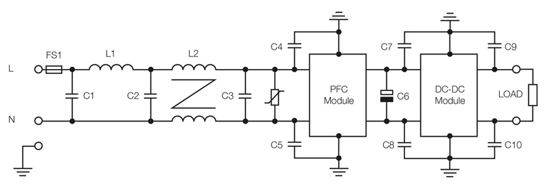
Figure 5: Schematic for AC input systems
Some combined single brick PFC and DC/DC modules are available, with external connections provided for the bulk capacitor. It is a requirement for AC input systems that creepage and clearance distances between line, neural, earth and input to low voltage output as stipulated by the relevant safety standard are adhered to during the design phase.
Any additional components also need to be included in the thermal management design to ensure that they stay within their thermal and safety limits. Temperature impacts electrolytic capacitor lifetime with a reduction of just 10 degrees centigrade doubling the service life making the choice of component design life, temperature rating and cooling arrangements critical to maintain the end equipment's desired service life. The use of thermally conducting pads and keeping thermally sensitive components away from higher temperature parts assists in maintaining overall system reliability.
The use of a baseplate convection-cooled power conversion module is an ideal approach for rugged environmentally sealed equipment and is a popular method for many transportation systems, defense applications, and mast head mounted network equipment.


.jpg)
