There are different techniques to increase a power supply’s hold-up time, each of which has advantages and disadvantages
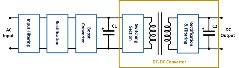
Figure 1: AC-DC power supply block diagram
During a storm, or when equipment is using a common power source shared with large machinery, the nominal AC input voltage may dip for a short period of time. This frequently happens when lightning strikes are in close proximity to a facility, or when large amount of current is drawn during a welding process on an industrial production line.
An AC to DC power supply, typically used to deliver a stable voltage to a machine’s control system, is designed to cope with a relatively short loss of its AC input. Typically this will not cause a loss or degradation of the DC output voltage, providing the duration (referred to as “hold-up time”) is less than 10 to 20ms. A longer period will deplete the energy stored in its electrolytic capacitors and the output voltage will dip, or turn off.
In industrial applications this could cause a machine on a production line to reboot, potentially losing process data, resulting in a production stoppage and loss of revenue.
Recent medical legislation has addressed risk analysis, to both the patient and operator, with the implementation of the EN 60601-1-2; 2015 (Ed4) immunity standard. With the increase in home healthcare, this standard requires testing with power interruptions between 20ms and 5 seconds. As it is impractical to expect a power supply to continue to operate for several seconds without AC power, this is often addressed using battery backup.
The aircraft industry has had the DO-160 standard in place for many years. Section 16 refers to power input, simulating conditions of aircraft power from before engine start (using auxiliary ground-based power) to after landing, including emergencies. The requirement is for a hold-up time of at least 200ms. Anyone who has flown in a commercial aircraft has probably noticed the cabin lights flicker when the plane’s power is switched over to the engine generators at the gate, but it does not make the entertainment systems reboot.
Increasing hold-up times
There are a number of techniques to increase a power supply’s hold-up time, each of which has advantages and disadvantages.
To best understand this, a brief review of how an AC-DC power supply operates is required. (Figure 1.)
On the left side is the AC input power, which is filtered, rectified and increased, using a boost converter, to approximately 390Vdc. The DC-DC converter section provides isolation from the AC and reduces the 390Vdc to the desired (lower) voltage. The main function of electrolytic capacitor (C1) is to store energy in the event of a brief loss in AC power and avoid interrupting the DC output.
The amount of energy stored in capacitor C1 is calculated as: ½ x C1 x V2. To increase the stored energy, and hence the hold-up time, either the amount of capacitance or the voltage on the capacitor has to increase. Since the voltage V is squared, an increase in the value of V will have a much greater impact.
To compare the methods of increasing hold-up time, a hypothetical system requiring a 200ms hold-up time, a load of 150W at 12V (with a minimum output voltage requirement of 11.5V) will be used.
1. Using a higher rated power supply and operating it at a reduced load
A higher wattage power supply will usually have a larger amount of capacitance (C1) than that of a lower wattage power supply. This is because more energy must be stored for a similar hold-up time.
For our example if we were to use TDK-Lambda’s RWS150B-12 power supply to provide the desired 12V at 150W, we would only have 30ms of hold-up time (Figure 2), which would be insufficient. Note from the plot that the greater the load, the quicker the energy stored in C1 is depleted. Conversely, the lighter the load, the longer the time C1 is able to provide energy.

Figure 2: Hold-up time versus output load for the RWS150B-12 power supply
To obtain 200ms, we could use the TDK-Lambda CUS1500M-12 rated at 1500W. (Figure 3).

Figure 3: Hold-up time versus output load for the CUS1500M-12 power supply
As the value of C1 in the CUS1500M-12 is much larger, if the power supply only supplied 10% of its rated output current (150W), the hold-up time would be over 200ms.
This is a very simple solution, but using a 1500W power supply would be larger and more expensive.
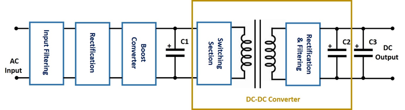
Figure 4: Adding load capacitance at the load
2. Adding capacitance across the power supply output terminals or load
Initially additional capacitance (C3) across the output may seem like an easy solution. Based on the equation 2 in the appendix, however, C3 would have to be a massive 4,595,745uF or 4.5 Farads! It would consume a lot of space and may result in the power supply failing to initially switch on. That level of capacitance would appear as a short circuit to the power supply.
C = 2 x Pout x t / (V2 – Vend2)
C = 2 x 150 x 0.18 / (122 - 11.52)
As a note, the power supply already has 20ms of hold-up capability, so it is reduced to 180ms (0.18s).
3. A customised power supply with a larger high voltage bus capacitor (C1)
As mentioned earlier, the energy stored in a capacitor is equal to ½ x C x V2, so adding capacitor C1a in parallel with our original capacitor C1 has a greater effect than adding capacitance across 12V output.

Figure 5: Additional high voltage bus capacitance
As C1a would be located on the primary side of the power supply, any changes to the power supply would require creating a custom or modified-standard design. This would involve engineering charges and incurring safety re-certification fees. It would also take time to make the modification and safety certify the power supply.
If the existing power supply has a hold-up time of 20ms, increasing it to 200ms would require adding the equivalent of nine more C1 capacitors. C1 typically occupies 5 to 6% of the internal space of a power supply, and so would increase the size of the power supply by around 50%, assuming the product height remains the same.
4. A 48V output AC-DC power supply and a wide range input non-isolated DC-DC Converter
A 48V output AC-DC power supply could be used with a non-isolated wide-range input 9 to 53V DC-DC converter set at 12V output. See Figure 6. These DC-DC converters often have efficiencies as high as 96%. C1 is not considered primary, making certification easier.

Figure 6: 48V power supply and a non-isolated DC-DC converter
The hold-up of the AC-DC power supply as 20ms, requiring an additional 180ms (t).
C = 2 x P x t / (Eff x (V2 – Vend2))
For our example, the required value of C1 would be 2 x 150 x 0.18 / (0.96 x (482 – 92)) which calculates as 25,304uF.
5. Using a “buffer” module
Buffer modules are off-the-shelf parts that again utilise electrolytic capacitors for energy storage. They also have built in inrush reduction and protection. TDK-Lambda’s ZBM20 series is suitable for 12, 15 or 48V outputs. They are simple to connect and can be paralleled for additional hold-up.

Figure 7: Buffer module connection
 Single.jpeg)