Author:
James Lougheed and Alan Elbanhawy, Exar
Date
09/16/2015
 PDF
PDF
The power module market has seen explosive growth in the past few years. With growth rates of roughly 30% compounded annually, it’s a trend that many people are watching. Power modules are a new breed of products in the market that are LGA or QFN based, closed frame power supplies that include the controller, driver, MOSFETs and inductor.
Historically, there have been two options for designers needing to deliver power within their system. The first was to roll their sleeves up and design a discrete power system confronting all the challenges involved. This option was good for a lower system cost and the flexibility to optimize the power system for the specific loads needed to be driven. The second was to utilize an open frame solution, often referred to as a brick or POL, which is a PCB-based power supply which afforded the engineer time to spend on other aspects of the design by essentially outsourcing the power supply design hassle.
This second option, however, was not possible for those designers with a strict BOM cost target or limited real estate – that’s most of us. These new breed of power modules drastically reduce the size of such solutions, eliminating the real estate barrier. They are smaller than what can normally be done by a designer discretely because of the ability for the supplier to work at the die level and consolidate under one package housing. Price is also reduced with the smaller size, board-space savings and lower insertion costs.
Leading the trend
There are two main types of customers who are leading this trend where the value of these new solutions has already been justified within their designs. First, there are those who like the open frame users, prefer to outsource the power supply design by buying a completed module so their engineering resources can focus on what adds value to the end product.
With more competition in the market for electronic products and with analog power designers becoming increasingly rare, this group is increasing every day. The other type of customers we see emerging are those who are under pressure for smaller, sexier, product form factors. This is very apparent in products where thin solutions are becoming the norm and the z-axis space is at a premium. This is not just happening in the consumer space but also in industrial, instrumentation and networking applications.
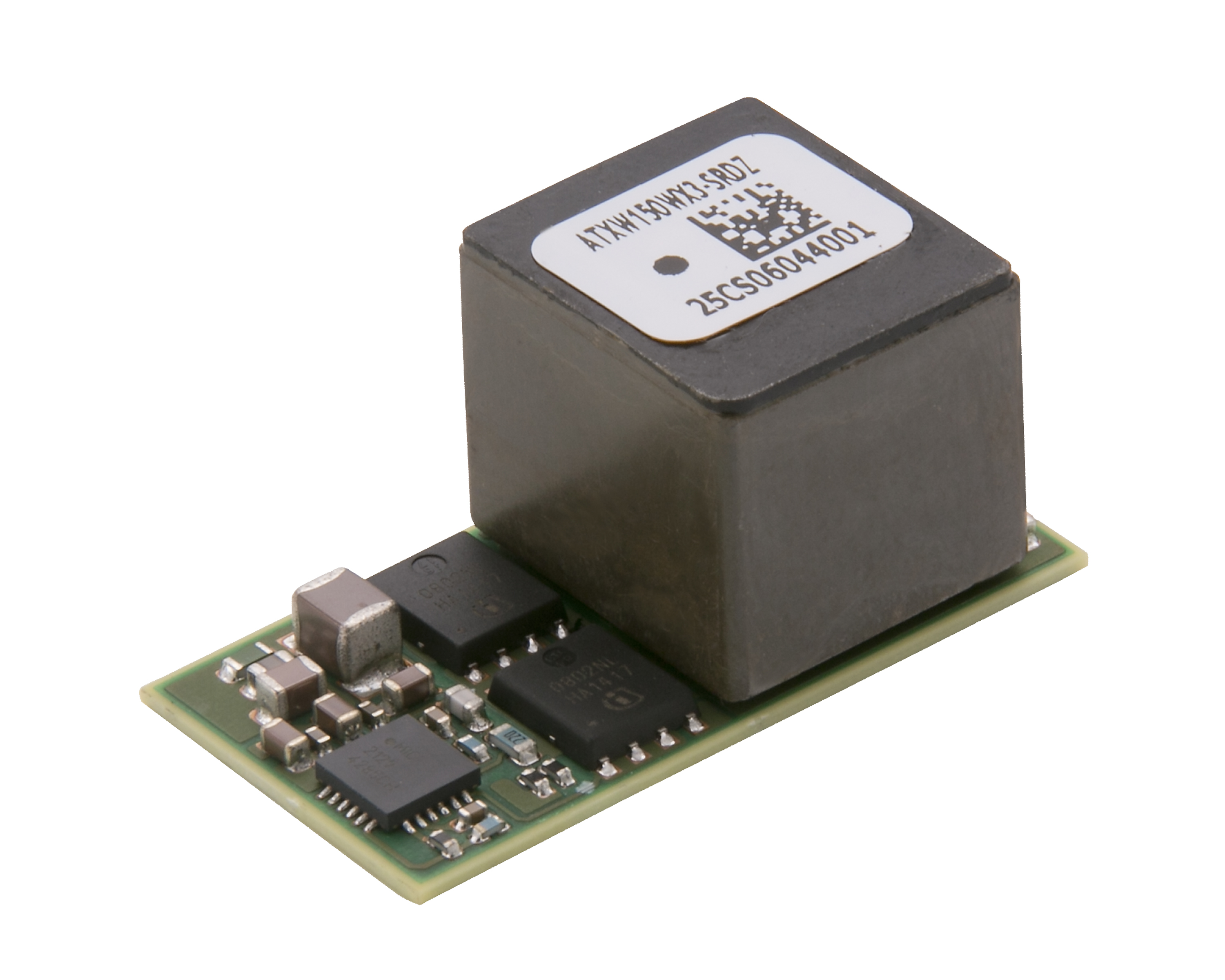
A great example of this new breed of products is the XR79120. This power module is a device capable of delivering 20A converting off a 12V rail, all in a condensed 12mm x 14mm x 4mm QFN package. Normally power module efficiency is a trade-off between size and efficiency, with larger drivers, MOSFETs and magnetics, higher efficiencies can be attained. However, the XR79120 can produce over 90% peak efficiency for a 12V to 1.8V conversion. With this efficiency and extremely small size, it offers best-in-class power density in this space.
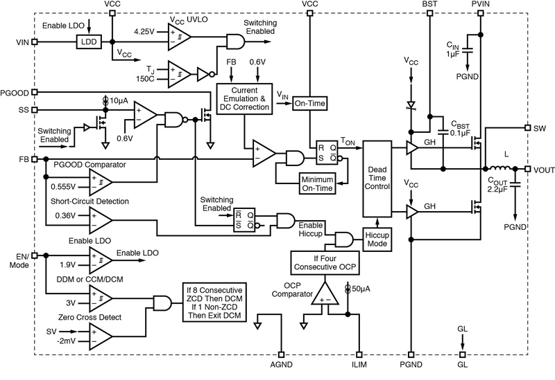
The controller is a proprietary emulated current mode constant on-time, COT, controller. This control topology offers substantial improvements over previous generations of controllers. They offer excellent transient response, load and line regulation. This architecture does not require any external compensation. This single feature alone lightens the burden of system design as it shaves weeks of compensation circuit design cycle to guarantee stable performance under all conditions of load, switching frequency and components tolerances. Figure 1 shows the simplified functional block diagram of XR79120.
Click image to enlarge
Figure 1. Functional Block Diagram
Operating seamlessly between Continuous Conduction Mode (CCM) and Discontinuous Conduction Mode, DCM, the controller features include:
-No control loop compensation
-Programmable 200ns to 2μs on-time
-Constant 400kHz to 600kHz frequency
-Selectable CCM or CCM/DCM
-Stable ceramic output capacitor operation
-DCM for high efficiency at light load
-CCM for constant frequency at light load
-Precision enable and power good flag
-Programmable soft-start
-Programmable hiccup current limit with thermal compensation
The controller was matched up with new generation MOSFETs in a very well-considered package layout, minimizing all parasitics while achieving the most optimum component interconnections. As the switching frequency can be selected up to 600kHz, the high side MOSFET was selected to offer a combination of very low switching losses and conduction or Ohmic losses allowing the efficiency to peak at 93%.
The inductors selection was extremely limited by the combination of the very small footprints but mostly by the 4mm maximum height of the power module. This height was dictated by many applications where they are mounted on the back of plugin boards or simply small form factor boards. Because of the high currents capabilities of these modules, the inductors combine DC resistance and to a lesser degree, core losses are the largest losses in the module and as such, great optimization effort went into their design.
The QFN package was selected because the higher output current and power require a package with the best junction-to-case thermal resistance, as well as flexibility in debugging prototype boards during design.
Key performance parameters:
-The XR79120 is a 20A module in a 12mm x 14mm x 4mm QFN package.
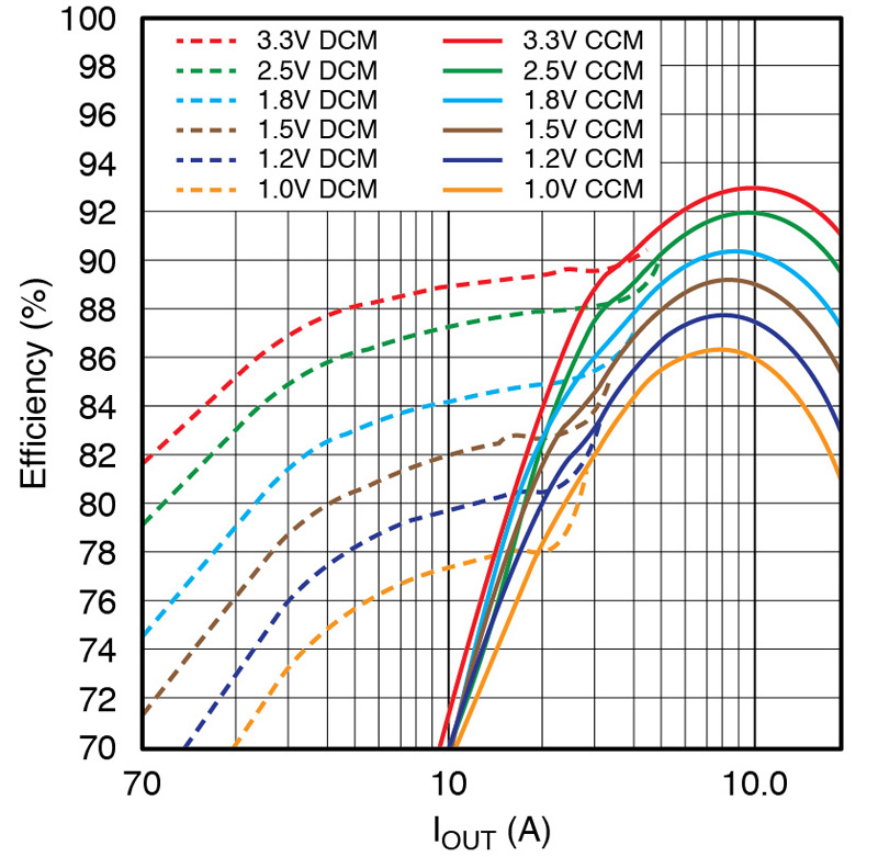
-High power conversion efficiency: because of the very small size of the package, high efficiency is mandatory to keep the maximum die temperature below the allowed maximum of 125°C. Figure 2 shows efficiencies of up to 93%.
Click image to enlarge
Figure 2. Efficiency at VIN = 12V and fs=600kHz
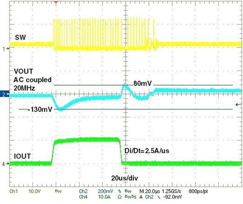
-Ultrafast transient response. Figure 3 shows a scope shot of a step load current of 0A-10A-0A. The control loop starts reacting within a few microseconds.
Click image to enlarge
Figure 3. Transient Response 0A-10A-0A
-Design once and use multiple times in applications simply by replacing a few passive components. This saves development time and R&D expenses and results in optimum time-to-market and maintaining the product competitive positioning.
-Matching of the control IC and the power train components on a very small package footprint of 12mm x14mm:
-Saves time sourcing, selecting and testing MOSFETs, inductors and capacitors.
-Saves time on PCB layout and potential re-spins to optimize efficiency, EMI and temperature rise of the application.
Thermal performance
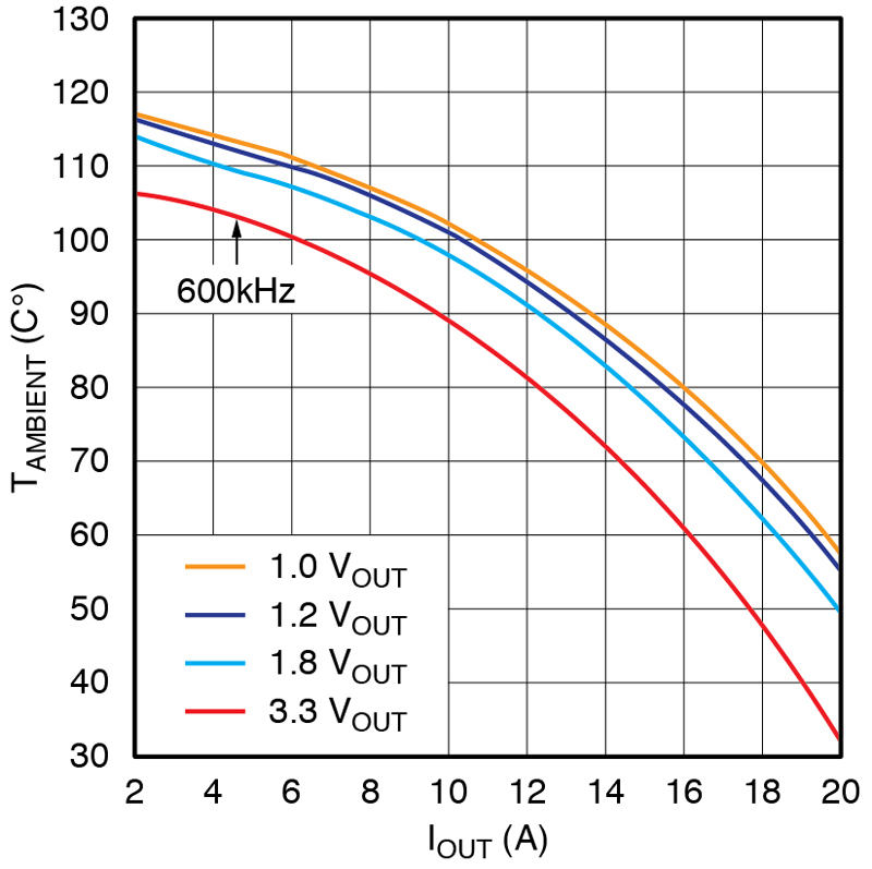
Figure 4 shows the de-rating curves of the XR79120.
Click image to enlarge
Figure 4. Maximum TAMBIENT vs IOUT, VIN=12V
As can be seen in the graph, the module can operate at full load of 20A with an output voltage of 3.3V, 66W at ambient temperatures of 48°C.
Devices such as the XR79120 along with the other parts in the family, XR79110 (10A) and XR79115 (15A), play an important role in modern power systems as they shortens the design cycle by using the guaranteed high performance power conversion, low cost and very high power density.