Here we’ll show how Spice can be used to provide proximity loss results for magnetics windings. Proximity loss equations are solved for a set of frequencies, and a simulation circuit is generated which predicts the proper AC losses regardless of the current waveform.
Inductor winding AC resistance calculation
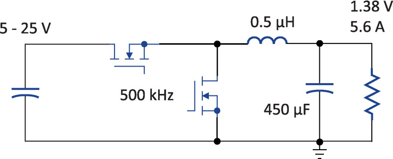
Figure 1 shows a buck converter for point-of-load applications. These converters are used in almost every area of electronics, and efficiency is an important issue. With the silicon solution being provided in a single package, the most important component affecting efficiency that a designer is free to choose is the output inductor. As we will see later, the high-frequency copper losses of the inductor can account for more than a 2% drop in efficiency. It is very important to understand the modeling and analysis of this effect.
Click image to enlarge
Figure 1: Sample Buck Converter for Point-of-Load Applications
It is well known that the resistance of copper increases with frequency. Just about every power electronics engineer has heard of the concept of skin depth where high-frequency currents flow on the surface of conductors. However, skin effect is just the beginning of the analysis. We need to use the more involved process of proximity effect to account for multiple layers of winding, or for conductors that are not straight wires.
In teaching workshops over the last 20 years, we have found that less than 1% of power supply engineers apply proximity effect calculations to their designs. This is due to the complexity of the process. Figure 2 shows the winding structure for the inductor of the buck converter circuit, together with Dowell’s equations, used to compute the increased resistance with frequency. As you can see from the graph, the resistance increases rapidly with frequency. We must take this effect into account when estimating the loss of magnetics windings.

Click image to enlarge
Figure 2: Inductor Winding Structure with Calculated AC Resistance Using Dowell’s Equations
A solution using Dowell’s equations is not an easy process. Fortunately, the POWER 4-5-6 power supply design software does this automatically for a given winding structure, and is easily used by all engineers. You can plot the AC resistance of a winding without understanding the equations themselves.
Once you have the AC resistance, the conventional approach is to take the observed current waveforms and extract the switching-frequency harmonics. There will be a DC term—the fundamental frequency equal to the ripple frequency—and then the odd harmonics of the switching frequency. The amplitude of the harmonics will vary based on the shape of the current waveform.
Equivalent circuit model and spice network
Calculating the harmonics of every waveform, and applying the various AC resistances to each harmonic is a tedious procedure for every operating point of your converter. Another approach is to generate an equivalent circuit model for the winding resistance increase. You can then use this model inside Spice to generate the complex analysis.
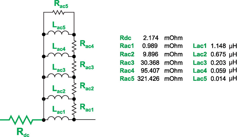
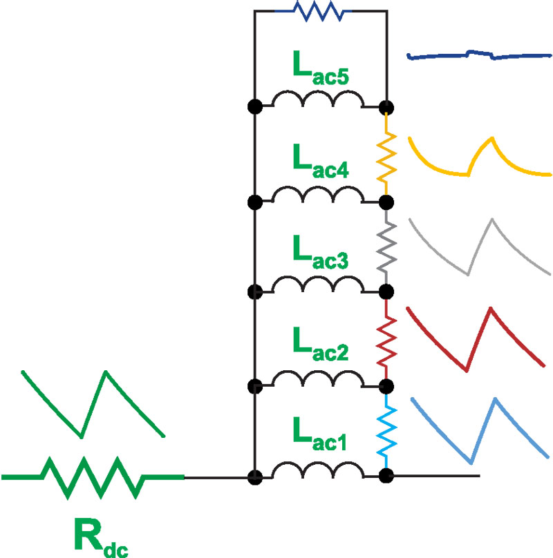
The winding of the inductor for the buck converter consists of 5 turns of helical copper foil around a ferrite core. Figure 3 shows the circuit model for the inductor windings. A series of R-L components models the increase of resistance with frequency. At DC, all of the inductors are short circuits, and the current only flows through the resistor Rdc. This is equal to the dc resistance of the winding. As the frequency goes up, more current will be shunted through the ac resistances, increasing the dissipation.
Click image to enlarge
Figure 3: Inductor-Resistor Network for AC Resistance Modeling. Values Generated Automatically by POWER 4-5-6 from the Inductor Winding Structure.
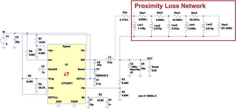
Figure 4 shows the proximity loss circuit incorporated into a full Spice model for the buck converter. Notice that the control chip used here, the LTC3611, is a variable frequency controller. The operating frequency can change with line and load. Once you have a circuit model, however, the variation in frequency will automatically be accommodated by the proximity loss network, producing the correct losses in the windings.
Click image to enlarge
Figure 4: Spice Schematic Including Proximity Loss Network
Spice simulation of proximity losses
The Spice circuit shown in Figure 4 was run for 10 ms to make sure that all waveforms were in steady-state, and all DC offsets caused by initial startup waveforms were zero. Surprisingly, the complexity of the proximity loss network did not have a very large effect on simulation time. With the proximity loss network, the time to simulate 10 ms of operation was about 5 minutes. Without this network, the simulation time was about 3 minutes.
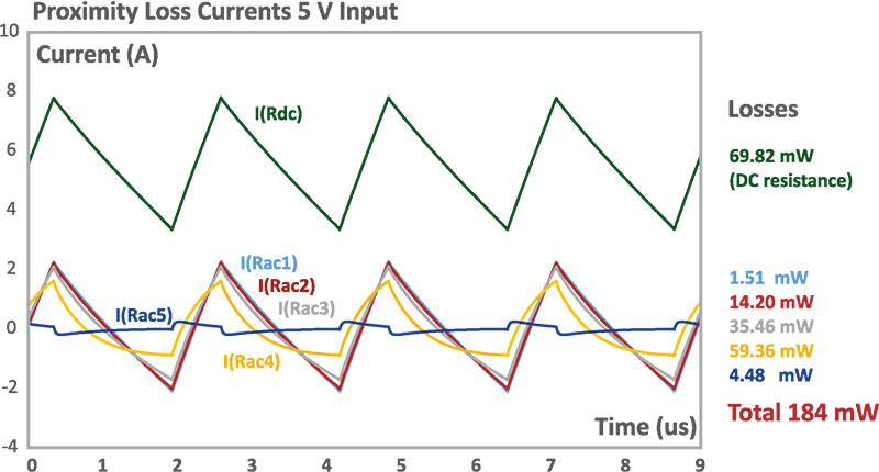
Figure 5 shows the simulated currents for the buck converter operating with a 5 V input. Only the current through Rdc, shown in green, has a DC offset, and this current is equal to the inductor current. Conventional losses are calculated by taking the rms value of the current through this resistor and multiplying it is by the Rdc value.
Click image to enlarge
Figure 5: Simulated Currents Flowing Through AC Resistances 5 V Input
Figure 6 shows the individual currents next to each of the ac resistances, clarifying where the currents are flowing.
Click image to enlarge
Figure 6: Simulated Currents Shown Next to Each AC Resistance
The ripple frequency flows almost unattenuated through the first three AC resistors as shown by the light blue, red, and gray waveforms. Each of these will contribute to additional loss in the windings due to proximity. The gold waveform also has a significant magnitude, and the resistor Rac4 gives the largest additional dissipation since that resistor is a high value. A small amount of current also flows through the final ac resistor, Rac5, not making a big contribution to the loss.
The total loss in the inductor winding is 184 mW, considerably higher than the 69.8 mW predicted by the DC resistance alone. While these numbers might not seem large, this is a low power converter and 100 mW of loss corresponds to a 1% drop in efficiency. Hence 1.8% efficiency loss is due to winding loss of the inductor and is a very significant number.
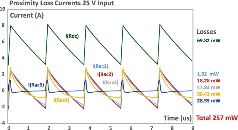
Figure 7 shows the simulation with a high line input of 25 V. Many things are now changed in the circuit – the duty cycle is much shorter, ripple currents are larger, and the frequency has shifted. Calculating the proper proximity loss from equations would be a very tedious process. However, the Spice simulation takes all of these effects into account with the proximity loss network. You can see that the currents through Rac4 and Rac5 have increased, resulting in higher dissipation numbers. The total loss has increased by about 70 mW, further lowering the efficiency of the circuit.
Click image to enlarge
Figure 7: Simulated Currents Flowing Through AC Resistances with 25 V Input
In all, the proximity effects increase the dissipation of the inductor windings almost 4 times. This number can be even higher when applying the same techniques to transformer windings where the AC component of the current is much higher.
Spice it up
Spice can be a powerful tool for magnetics analysis. A simple proximity loss network can be used to allow Spice to find Dowell’s equation solutions for any arbitrary current waveform. This makes Dowell’s equations easily accessible to all designers, regardless of experience level.
References
[1] POWER 4-5-6 design and simulation program for power supplies, www.ridleyengineering.com/software.html
[2] Impedance measurements for magnetics, www.ridleyengineering.com/analyzer.html (Click on Applications Tab)
[3] Join our LinkedIn group titled “Power Supply Design Center”. Noncommercial site with over 6500 helpful members with lots of theoretical and practical experience. www.linkedin.com/groups?&gid=4860717
[4] See our videos on power supply and magnetics design at www.youtube.com/channel/UC4fShOOg9sg_SIaLAeVq19Q
[5] Learn about proximity losses and magnetics design in our hands-on workshops for power supply design www.ridleyengineering.com/workshops.html

 PDF
PDF