Picking the Right L for your LED driver
A wide variety of driver circuits is needed to support new LED applications and the demands for high performance are challenging designers to be as creative as possible with new circuit techniques. In order to fully optimize the new circuits, a strong understanding of component performance is necessary. In particular, inductor selection remains a key part of the design process and with the right tools, identifying the best inductor can be one of the most fruitful areas for optimizing LED driver circuits, and with power converters for all applications.
For DC-DC LED drivers there are uses for buck, boost, buck-boost and SEPIC topologies. There are some requirements particular to driving LEDs, such as the need for a constant current source. In addition, many drivers use pulsed outputs for dimming capability, as well as to achieve higher efficiency, taking advantage of the phenomenon that the human eye does not perceive flicker above a certain frequency. Yet for all the variations, there are many commonalities among inductor based LED driver circuits. Whether they drive a single LED or a string, whether they have dimming capability or not, the essential inductor operation will be a function of the switching frequency, load current, and the input to output voltage ratio. These inputs feed the basic inductor relationship common to all DC-DC converters that is V = L x (di/dt). This relationship, along with different mechanical requirements will determine the type of inductor chosen. It is easy to imagine, for example, that the space constraints may be much different for a high brightness LED flashlight than for an LCD display backlight.
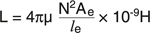
Understanding the tradeoff between inductor size, performance, and cost, begins with a brief review of inductor operating principles. It can be shown that these basic principles translate directly from inductor performance to the data sheet specifications that designers must use to choose between components. The design task for a power inductor is to maximize the inductance (L) and saturation current (Isat) product, otherwise known as volt-seconds, while at the same time minimizing the losses. The formula in figure 1 shows that inductance is determined by a combination of material properties and geometry.
The permeability (m), is a specific property of the chosen core material, whereas the effective cross-sectional area ae and the effective magnetic path length le, describe the core geometry. It is important to note that while it seems obvious that a larger core cross-section increases the inductance, it is a little more counterintuitive that a larger le decreases the inductance. This would be the case in a larger diameter toroid core, for example. As shown in figure 2 we can describe the saturation current in terms of the same physical parameters as the inductance.
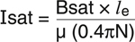
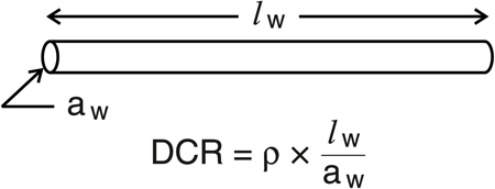
Similar to the inductance, the saturation current (or volt-seconds) depends on geometry (le ) as well as material properties, namely the saturation flux density (Bsat) and the relative permeability (m). Note that Isat is inversely proportional to the permeability, directly opposite the effect it has on inductance. As this suggests, optimizing the inductance value and optimizing the saturation current rating will be in conflict with each other. The Isat becomes the specification for how much peak current the inductor must be rated. The average current rating, on the other hand is loss dependent. To completely understand inductor loss, such phenomena as skin effect, core loss, and other frequency-dependent losses must be considered, but a good starting point is to consider the DC resistance (DCR). We commonly think of this as a single value found in a wire table, but it too is a function of both material property and geometry. The material property is the resistivity (r), and the length and cross-section of the winding wire are the geometric dimensions.
The DCR, Isat, and L equations demonstrate that these properties correlate differently to the same physical parameters, presenting a challenge to optimize for all three properties. For example, increasing the core cross-section will increase the L and Isat, but detrimentally increase the DCR. Increasing the core permeability will correspondingly increase the inductance and reduce DCR, but conversely Isat will be decreased. The end result is that any design must be a combination of these factors and no one design will provide optimization in all parameters. It is key, therefore, that the designer have access to selection tools that identify the combination of parameters best suited to a particular application. Those tools should include clearly defined specifications and some method for sorting/finding an inductor that best fits those specifications.
To demonstrate how the required circuit performance can be translated in to the necessary inductor specifications for inductance, peak current, and average current ratings, consider the example of driving a single white LED at .2A drive current and forward voltage of 3.3V, from a Li ion cell over the range of 3.3V to 4.5V. Further, as is typical for a portable device, assume the footprint and component height are limited. Vin = 3.3 to 4.5VDC Vo = 3.3VDC Io = .2A F = 400kHz Z = 1.5mm max. X x Y = 4mm x 4mm max. For this voltage step-down application, the required input for calculating inductor parameters for a buck converter is shown highlighted in figure 4.
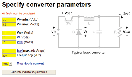
This information and V = L x (di/dt) is all that is required to calculate the required L value, along with peak current (Isat) and the average current (Irms) inductor ratings. Figure 5 shows the result for this example.
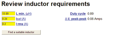
The inductance calculation is based on the amount of inductance required to minimize the desired output ripple current and maintain continuous current conduction in the inductor. The effective output voltage ripple is a result of the current ripple times the ESR of the output filter capacitor. In general, the ripple for LED drivers does not have to be as low as for many other applications. The Isat specification shows the minimum peak current rating the inductor must have in order to insure against core saturation, otherwise when saturated the inductance will drop and the converter operation will not be as expected. The Irms rating indicates the average current that will flow through the inductor, which in the buck converter is the same as the average load current. The peak-peak ripple current included in the calculations, will be needed later for calculation of frequency dependent losses. The inductor specifications having been determined, the next step is to identify a real component that meets these requirements. Based on the L and current specifications, and the physical size constraints, the Coilcraft Inductor Finder tool returns a list of suitable inductors.
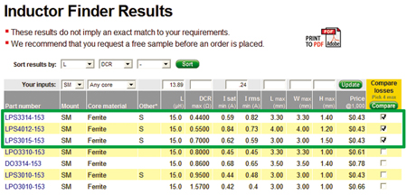
Having multiple options is necessary to make an optimal match for the application. Consider the first three choices. All three parts meet the requirements. The footprint dimensions range from 3.3mm to 4.0mm and the heights are 1.2mm, 1.4mm, and 1.5mm. One could certainly make a selection based on the size, if that is most important for the application. If component height is most important, then the LPS4012-153 is the best choice, whereas the LPS3015-153 is the winner if saving printed circuit board space is more important. Assuming all of these sizes are acceptable, there are other considerations. Many LED applications are developed specifically for the purpose of saving energy, so choosing the component with the best average power loss is an important consideration. Of the three parts, the DCR ranges from .44W to .70W, certainly a wide swing that would suggest LPS3314-153 as the choice for most efficient operation. Conversely, for many converter designs it is desired to have extra Isat rating in order to accommodate load surges or short circuit conditions, which would place greater emphasis on finding the inductor with the highest Isat rating. There are more opportunities for optimization beyond the values shown in the table. One of the most common decisions to be considered for any dc-dc converter including LED drivers is switching frequency, balancing the smaller component size enabled by high frequency against the generally better efficiency at lower frequency. The Coilcraft Core and Winding Loss Calculator gives a quick and easy way to judge the potential performance gain at different switching frequencies. Predicted losses can be calculated based on the combination of switching frequency, average current, and peak-peak ripple current. For this example the results are summarized in figure 7.
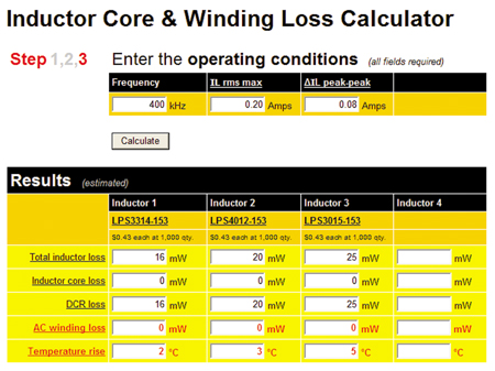
For these operating conditions, no core loss is predicted nor is ac winding loss. The predicted loss is entirely made up of the DCR conduction loss. This situation suggests that the inductors could operate at much higher frequency before introducing significant core or ac winding loss. In fact, examining the inductors at 4MHz instead of 400kHz, does show core loss increasing. The three inductors chosen have roughly the same efficiency and any would likely be suitable for this application. The designer is free to make the final selection based on other factors - footprint, height, availability, cost, etc. Of course in this example, we have simply examined the impact of operating the same inductors at higher frequency. In order to truly take advantage of the higher frequency, the same tools and procedure should be used to re-calculate the (smaller) L needed at higher frequencies and determine the options for using physically smaller inductors.
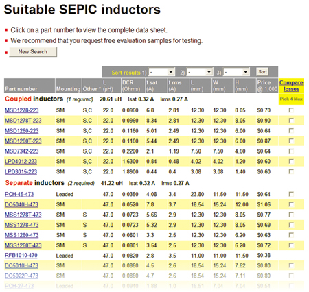
For portable applications, not only is high operating efficiency desired, but it is also important to operate from as wide a voltage range in order to give the longest battery life per charge cycle. In the previous example the minimum input voltage was limited to 3.3V, but for a typical lithium ion source it would be desirable to operate as low as possible on the discharge cycle, typically as low as 2.7V. This places the 3.3V output inside the input voltage range, no longer making this a purely step-down application. One very popular topology for this situation is the SEPIC converter, which uses two inductive elements to provide step-up/step-down capability. In this case the calculations are again based on V = L x (di/dt), with the added stipulation that the two inductances are calculated separately, having some performance analogous to transformer operation in which the input and output windings have different current requirements. While it is possible to use physically separate devices for the input and output inductors, using two windings coupled together on one core as a single device saves valuable pc board area and has the added benefit that only one half the inductance is required per winding to achieve the same performance. Using the Coilcraft SEPIC Converter Inductor Selector for this example, with input voltage range extended down to 2.7V, provides the needed inductance values along with the current rating for each winding as shown in figure 9.
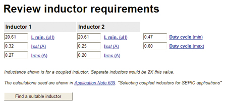
It is seen in this result that a little more inductance is now required due to the lower input voltage and the different current ratings are shown for the two windings. Note that the Inductor 2 average current is exactly the same as the load current. Similar to the buck regulator inductor, both are series connected to the load. The results shown in figure 10 are for separate inductors. Only one half the inductor value is required if the inductors are coupled on the same core. Figure 10 shows the solutions available for this SEPIC converter, both coupled and separate inductors.
LED drivers require new circuit techniques to meet high efficiency performance goals. In order to meet these goals in applications that are often tightly space constrained, inductor selection can be crucially important. Fortunately for today's user, many inductor shapes, sizes, and types are available, along with the tools necessary to identify them. www.coilcraft.com


