Interference-free cabling
Long lines for distributed loads can emit and be susceptible to interference which can affect the connected loads. However, the loads work without disruption as long as a few basic rules are observed when it comes to cabling.
Moderndevices and systems are generally complex, their electrical/electronic components are modular in design and they are often spatially distributed. The effect of wiring and long lines for individual modules must be considered. The greater the spatial separation, the greater the resulting effects.
In such systems certain conditions apply to the power supply in particular. For example, mutual EMC interference through inductive and capacitive coupling needs to be avoided as well as the mutual effects of the loads.
Furthermore, the characteristic output voltage of a power supply unit or DC converter is often incompatible with the load characteristic. Consideration should also be given to the probability of system failure which is affected by the modular distribution of power supplies.
Distributed power
Distributed power means the central provision of power to distributed loads in one building, plant, system or large device. Examples include lighting, automatic doors and windows in houses, flats, industrial plants, or complex systems. Such systems usually generate harmless direct current with a central low voltage power supply, which is then distributed to the connected loads, sometimes via long lines. In many cases, this reduces cabling and administrative costs. Given the low voltage and low short-circuit currents, insulation costs and line cross-section requirements are also lower and wiring is more cost-effective. For example, a single power supply unit is usually more economical than multiple units with the same capacity.
Power supply units must comply with the statutory limits for emitted and in particular, conducted high-frequency interference in supply lines. However, there is no statutory regulation of the general interference values for the output lines of power supply units.
The user is therefore responsible for ensuring the suppression of interference. This is no problem for compact devices. However, if the output voltage is distributed using long lines, this becomes an issue that cannot be ignored. TRACO POWER therefore offers power supply units that filter radio interference specifically for output lines similar to the filtering of mains interference on the input side. With this approach, compliance is achieved with the requirements of EN 55022 (Telecommunication Ports) and EN 55014-1 (Household Appliances).
Avoiding malfunctions
Long lines for distributed DC loads may not only emit interference, but could also absorb it, as the lines function like antennae in both directions. Such radiated interference could cause interference voltage and current in the load lines which in turn could cause malfunctions in the connected loads. A few important rules must be followed in order to keep filtering requirements to a minimum for connected equipment and loads. For example, lines should not be laid over long distances in parallel to lines with high currents or high current fluctuations.
Conducted interference emitted from one connected load which affects another, could also lead to malfunctions. The circuit for a load line can be simplified by using an ohmic resistor and inductive reactance.
Click image to enlarge
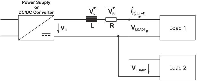
Figure 1: The simultaneous supply of power to loads via a shared line with ohmic and inductive impedance can cause interference.
If two loads are connected to this line and, for example, a rapid load change occurs in the first load, this will cause an ohmic and inductive voltage drop in the load line. Induced voltage is set up here in such a way that it tries to maintain the previous state. However, this can cause extremely high peaks in load input voltage for the second load and lead to it malfunctioning.
Clcik image to enlarge
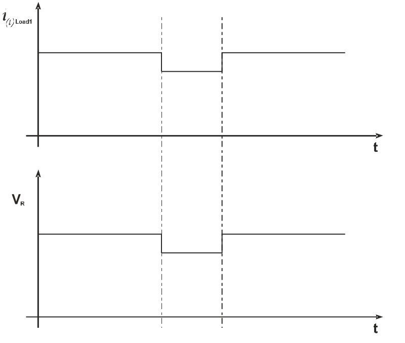
Figure 2a: Load jump caused by the first load

Click image to enlarge
Figure 2b: Input voltage at the second load in the event of a load jump for the first load
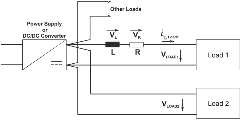
Line inductance is reduced by twisting the load lines, which ensures a lower number of interference voltage peaks. If the line cross-sections are suitably sized ohmic voltage drops can usually be ignored. Star-point wiring avoids this problem altogether,as all loads are connected close to the power supply unit. This prevents any mutual influence caused by load changes in the load lines.
Click image to enlarge
Figure 3: Star-point wiring connects all loads close to the power supply unit.
Disruptive ground loops
Interference also often occurs in supply, control and sensor lines as a result of so-called ground loops. The term originates from the era of tube radios. This wiring error was observed as a buzzing in the loudspeaker. It occurred in DC loads that had been connected via long lines to a power supply unit which was located in a different room from the load.The neutral lines of the AC mains supply network are typically earthed at both the power supply and the load in accordance with applicable installation rules. The earthing of safety low voltage is entirely customary and usual in the industry in order to ensure safe disconnection by tripping the fuse in the event of malfunctions when hazardous voltages arise in safe extra-low-voltage lines (SELV).
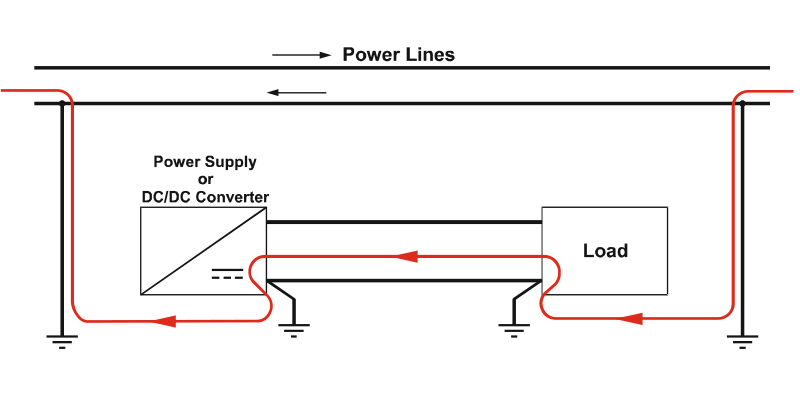
Click image to enlarge
Figure 4:A DC load is connected via a long line to the power supply unit.The neutral lines of the AC mains supply network are typically earthed at both the power supply and the load in according with applicable installation rules.
The disadvantage of this protective measure is that there are two shared return lines in parallel for both power supply systems. Currents are distributed in accordance with line resistance. This may, among other things, cause a relatively large alternating current to flow into the return line that is actually only designed to handle direct current. This current can lead to voltage fluctuations that could cause the load to malfunction. Such ground loops should therefore be avoided by using single-point earthing or providing galvanic isolation of potential using local DC/DC converters.
If these problem sources are taken into consideration for wiring, multiple distributed loads can be supplied with power from one power supply unit in a cost-effective manner, even via long lines. Distributed power without interference is possible, but certainly requires you to take a few precautions.