Author:
Reported by Cliff Keys, Editorial Director & Editor-in-Chief, Power Systems Design
Date
03/06/2012
 PDF
PDF
Click image to enlarge
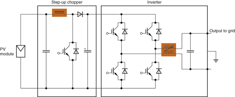
At least two power reactors are needed for solar inverters: one in the boost converter (step-up chopper) and one at the ouput of the inverter for EMC filtering. Besides the IGBTs, the losses in the reactors are a major determining factor of the overall efficiency of the inverter
Low-loss and high saturation flux density core materials in reactors and transformers are a key determining factor for the efficiency of inverters. The new TDK PE90 ferrite is a cutting-edge material that minimizes reactor losses in the step-up chopper and smoothing circuits of inverters for photovoltaic systems, thus enabling decisive increases in conversion efficiency. State-of-the-art inverters and power conditioners for photovoltaic systems have at least two reactors that are vital for the power conversion processes. One reactor is needed for the boost converter (step-up chopper circuit) and one is needed for output EMC filtering or smoothing (Figure 1). The future goal for modern inverters is to achieve an efficiency of 98 percent and higher. Conventional core materials cause reactor losses of around 0.5 percent of the output power for each reactor. Until recently, this was not considered significant. In the increasingly competitive solar market, however, these values negatively impact on a system's marketability. Thus, the design of the reactors and the transformers is becoming an ever important focus of manufacturers of inverters and power conditioners. If the reactors and transformers are to help make inverters more efficient, they must exhibit a saturation magnetic flux density that is high enough to support the peak current of inverters in the 3.3 to 5.5 kW class, which are widespread for household photovoltaic systems. They must also have much lower core losses than can be achieved with conventional core materials such as silicon steel sheets or sendust. A solution for this application is the advanced TDK PE90 ferrite material with excellent loss and saturation flux density properties.
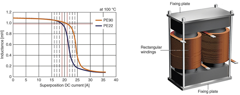
Advanced TDK PE90 ferrite opens new possibilities The new TDK PE90 ferrite represents a further development of the existing high saturation flux density material PE22. The two materials were tested in a prototype reactor with dimensions of 109 × 55 × 115 mm�. The adjusted air gap values and inductance values of PE22 and PE90 were at a similar level (1.1 mH), and the DC superposition current peak value, which is determined by magnetic saturation (inductance decreased by 10 percent from IDC of 0 A), was adjusted to around 20 A. DC superposition characteristics, which determine the current capability of reactors and transformers, are a vital factor for their design. While the conventional high saturation magnetic flux density material PE22 reached magnetic saturation at 19 A, the newly developed PE90 could still function as a reactor at up to 21 A, a level about 10 percent higher than that of PE22 (Figure 2). Furthermore, the core loss of TDK PE90 material at 100 °C was 23 percent lower than that of PE22, which makes the rise in magnetic flux density steep, and the minor loop's linearity was maintained right up until it was saturated. In other words, PE90 is an outstanding power ferrite with high saturation magnetic flux density Bs and is the first such material to qualify as a low-loss material. As a result, it is now possible to replace reactors that employ soft magnetic metal with reactors that use TDK PE90, without changing the size.
Cutting reactor losses by up to a third The advantages of TDK PE90 ferrite are even clearer when compared to conventional materials such as silicon steel sheet and sendust. A comparison of the actual performance of the reactors integrated in the power conditioner based on their total iron and copper losses demonstrates the superiority of TDK PE90 over conventional materials. In a simulation of the reactors used for the smoothing circuit of the inverters for 3-kW photovoltaic system PE90 material cores exhibit 33 percent lower losses than a similar sized silicon steel sheet reactor and approximately 30 percent less than a similar sized sendust reactor (Figure 3). Enabling high frequency inverters with smaller reactors Most inverters that achieve 95 percent efficiency or higher employ trench IGBTs, which provide high-speed operation and low loss properties. But these IGBTs, with a built-in high-speed soft recovery diode, are able to support switching up to approximately 30 kHz, which is beyond the operating frequency range of silicon steel sheets and sendust. Moreover, the latest IGBTs for high power applications feature significantly lower losses and are much faster, enabling 30 to 50 kHz drive elements that are in line with the high-speed switching requirements of power conditioners. Conclusion If all of the installed reactors, including those for step-up choppers, are designed with the advanced ferrite material TDK PE90 with its superior core loss frequency characteristics, the operating frequency of inverters can be set at 30 to 35 kHz rather than the currently standard 15 to 20 kHz. Nearly doubling the operating frequency range makes the use of silicon steel sheets and sendust difficult. Even in the higher frequency range, the core loss of TDK PE90 remains much lower than that of the sendust material at 15 to 20 kHz. While the copper loss increases at the higher frequencies, the magnetic flux density required decreases, which means that the core size can be reduced. As a result, the use of TDK PE90 as core material will enable even more efficient inverters with even smaller reactors to be designed. www.global.tdk.com