Improving Signal Measurement Accuracy
Properly implemented, galvanic isolation is an effective defense against disturbances in the ground plane often referred to as ground loops, which occur as a result of varying electrical potentials.
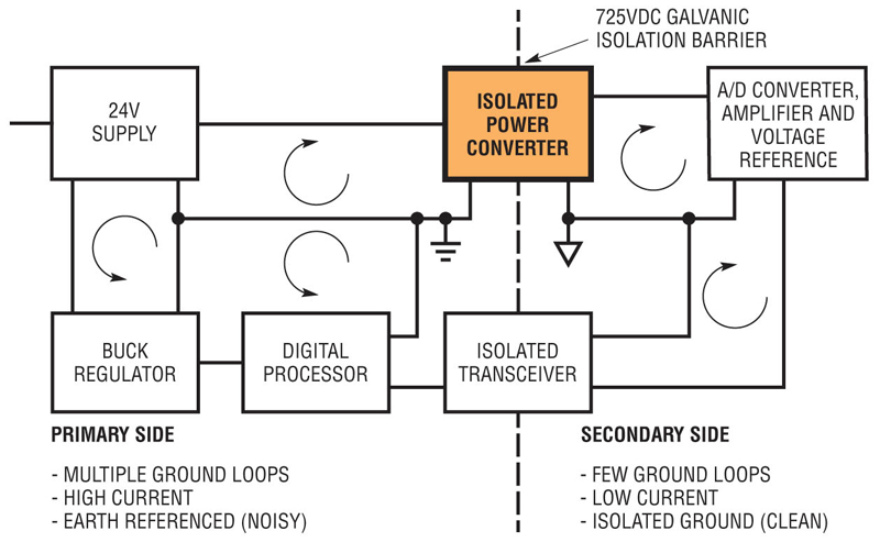
Physical limitations require that electrical components on a PCB connect to the ground plane at different physical locations. As a result, pockets of varying electrical potentials are created when each components’ ground plane connection acts in combination with circuit board parasitics. Another significant contributor to the creation of ground loops is conducted EMI created by high current motors, pumps, switching regulators and digital processors with their characteristically fast changes in power demand often in the tens of amperes of current (Figure 1). These ground plane disturbances can result in significant measurement inaccuracies. The ground potential where the measurement sensor is located may not be the same as the ground potential where the ADC converted the analog signal to a digital signal. Thus the resulting digital signal is now skewed by the voltage delta between the two ground potentials. While compensation for the delta could theoretically be added at the signal processor, the magnitude of the ground potential delta changes over time as neighboring loads constantly vary their current consumption. This situation makes compensation a challenging proposition at best. Moreover, isolation offers protection for down-stream devices from potentially damaging supply rail transients or short circuit events.
Galvanic Isolation Applications
Dividing a large control system circuit design into smaller galvanically isolated compartments is a smart strategy to protect components the risks of damage from electrical overstress. The isolation barrier prevents any transfer of electrically charged particles therefore communication between compartments would be performed using other means such as optical, wireless, capacitive or magnetic methods. Any supply rail and/or ground disturbances can easily damage low power 5V or less sensor units comprised of ADCs, amplifiers, voltage references and transducers, which often have a combined power consumption below 1W depending on performance. As a precautionary measure, 500VAC (~710VDC) of galvanic isolation is inserted to protect these devices should a short cause the input supply voltage to exceed the components’ absolute maximum voltage rating. In the event of such a failure, the resulting damage is limited to a small compartment or section of the overall control system. Additionally ground disturbances are also minimized which will be discussed in the next section. The damaged sub-sections may then be stocked or purchased as standard “off-the-shelf” replacement units enabling a complete system recovery in a shorter amount of time with less effort.
Click image to enlarge
Figure 1: Isolating power & ground rails for sensitive data converters, amplifiers & references from other high current power paths improves signal resolution & reliability
The Right Balance of Power
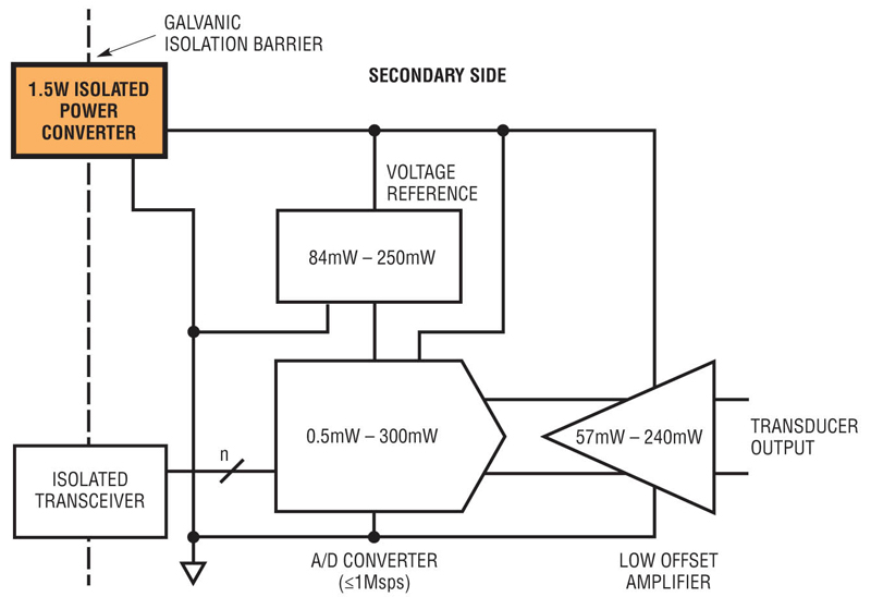
Isolated power converters preserve signal accuracy by creating an electrical barrier between noisy high current and low current sections of the system where a cleaner more stable ground is available. In particular isolated DC/DC converters delivering under 2W provide sufficient power for one or more sensor units consisting of an amplifier, ADC converter, transducer and voltage reference (Figure 2). While isolated compartments consuming more than 2W may start to experience the same ground loop issues which called for galvanic isolation in the first place. Furthermore, as the isolated compartment increases in complexity, the additional wires and PCB traces inside become more susceptible to electrical noise generating sources such as radiated EMI from neighboring electronics. Given a stable ground plane protected by an isolation barrier, more accurate readings can be made by the sensor unit, improving system control. Accuracy may even be improved to the point of permitting system performance upgrades with higher resolution ADCs.
Click image to enlarge
Figure 2: Power Consumption range for each component in a sensor unit consisting of amplifier, ADC, transducer & Reference. Total power consumption is less than 1W.
Limitations of Conventional Isolated Converters
Conventional power converters employed for 500VAC (~710VDC) isolation have a limited ability to support industrial and commercial applications. Many have a maximum internal operating temperature of +85°C. Including the effects of internal power losses and package thermal resistance, the output power of a conventional converter may start de-rating at an ambient temperature between +50°C to +65°C leaving little margin. Cooling systems can provide some assistance, however it raises other concerns in terms of cost, size and reliability should the fans fail. Other isolated solutions require a ±10% accurate 12V or 24V input which is incompatible with power from an unregulated power supply or an industrial Li-Ion battery whose usable voltage range varies by ±12% to ±14%. While conventional isolated converters offer common fixed output voltages such as 3.3V and 5V, they do not provide any flexibility to accommodate the 0.1V or greater dropout voltage of an external 3.3V or 5V reference nor a similar output voltage LDO post regulator. The latter may be implemented to reduce input power ripple for an A/D converter. As control systems become more complex, additional isolated sensor compartments are required to support a greater number of signal channels providing further information on system performance. At the same time board space is limited requiring a smaller solution size to fit more features into less space. A new advancement in isolated DC/DC power converters addresses these concerns.
Conventional Isolated Converter Limitations:
· Maximum Internal Operating Temperature of +85°C Limits Output Power
·in High Temperature Industrial Environments
· ±10% Input Supply Requirement Hampers Operation from Unregulated Power Supplies or Batteries with ±14% Voltage over Operating Life
· Internally Fixed Output Voltages do not Accommodate Dropout Voltage for 3.3V / 5V Output Voltage References nor LDO Post Regulators
New 500VAC (~710VDC) Isolated Converters
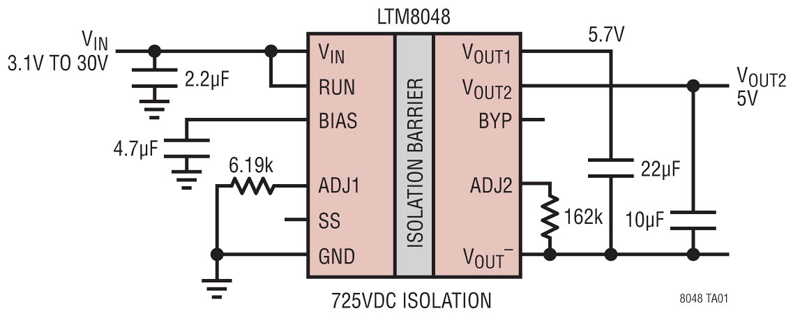
A solution which addresses these limitations is the LTM8048, a 725VDC isolated µModule® power converter. A space saving 1.5W output solution, the LTM8048 includes the power switch, controller, transformer, and compensation in a 9 x 11.25 x 4.92mm BGA package requiring few external components (Figure 3). The converter offers advancements in operating temperature, input and output voltage range compared to conventional isolated power solutions. Guaranteed to operate up to an internal temperature of +125°C, the 1.5W rated LTM8048 is better suited for operation in industrial and commercial applications such as natural resource delivery infrastructure, turbine, battery management, and security equipment. The wide input supply voltage from 3.1V to 32V allows the LTM8048 to be powered directly from less expensive unregulated switching power supplies or a wide range of battery stacks. Moreover, the primary side input voltage on the converter may be above, equal to, or below the desired output voltage on the secondary side. An internal LDO offers any output voltage from 1.2V to 12V adjustable simply by applying the appropriate resistor between the LTM8048’s feedback pin and the secondary side ground. The output voltage features a ripple of less than 1mV providing a stable power rail for ADCs and analog sensors for more accurate and repeatable measurements. The internal 725VDC galvanic isolation barrier suitable for 500VAC (~710VDC) requirements is 100% production tested for guaranteed circuit protection.
A Glimpse inside the LTM8048
Within the LTM8048 is an isolated flyback controller, power switch, 725VDC isolated transformer, a modest amount of input and output capacitance, compensation and a low output ripple linear regulator supporting up to 1.5W of output power (Figure 4). The controller architecture and voltage feedback loop allows the LTM8048 to create an output voltage on the secondary side that is above, below or equal to the input voltage.
Some isolated controller ICs use opto-isolators or extra transformer windings to feedback voltage information. Opto-isolator circuits waste output power and the extra components increase the cost and physical size of the power supply. Moreover, Opto-isolators can also exhibit trouble due to limited dynamic response, nonlinearity, unit-to-unit variation and aging over life. Circuits employing extra transformer windings experience an increase to the transformer’s physical size and cost, and dynamic response is often mediocre. In contrast, the LTM8048 control loop examines the switch voltage reflected to the primary side of the transformer to ascertain the secondary side voltage when the secondary side current is near zero. This novel approach to regulation enables the LTM8048 to support a wide range of secondary side output voltage which is selected simply by adding a resistor.
A switching cycle begins with the internal switch turning on. The inductor current increases until an internally set current limit is reached. The voltage across the power switch rises to the output voltage divided by the secondary-to-primary transformer turns ratio plus the input voltage. When the secondary current through the diode falls to zero, the voltage across the power switch pin voltage falls below VIN. A discontinuous conduction mode (DCM) comparator detects this event and turns the switch back on. Therefore, a smaller transformer can be used compared to an isolated converter, which always operates in continuous conduction mode.
An internal low output ripple linear regulator on the secondary side creates a low ripple power supply rail to support high accuracy A/D converters and low offset amplifiers. With the addition of an optional 0.01uF reference bypass capacitor the output voltage ripple decreases to less than 1mVp-p and 20µVRMS over a 10Hz to 100kHz range (Figure 5). Additionally, this reference bypass capacitor will improve the transient response of the regulator. Output voltage accuracy over the full temperature range is ±2.5%. The linear regulator is protected against reverse input and reverse output voltages.
Design innovations led to development of a compact 725VDC isolated transformer enabling a significant size advantage in the construction of the LTM8048 Isolated µModule Converter compared to other solutions. For added peace of mind, the module is 100% tested in production with 725V applied in both polarities for one second each.
To ensure consistent performance under the most demanding conditions, the LTM8048 is backed by rigorous reliability testing the results of which are posted online in an extensive report showing no failures to date. Reliability tests conducted include operating life, temperature cycling, thermal shock and board mount vibration to name a few. The LTM8048’s BGA package is well suited for use in electronics targeted for high vibration environments. Furthermore, each LTM8048 converter endures extensive production testing at the extremes of the operating temperature range with particular care extended to the MP-grade rated for the -55°C to 125°C range (LTM8048MPY#PBF).
Click image to enlarge
Figure 3: LTM8048 typical application
Conclusion
Isolated power is a proven method to protect and preserve the accuracy of low power sensor units comprised of ADC converters, references, amplifiers and transducers whose performance may otherwise be adversely affected. Correct and reliable data gathering by the sensor units is critical to control system operation. In most cases, the entire sensor unit consumes less than 1W using the latest components. Although conventional low power galvanically isolated DC/DC converters have provided a trustworthy and effective barrier they have shortcomings in the areas of input voltage range, output voltage range, maximum operating temperature and size. A new 1.5W µModule isolated converter broadens the application possibilities by offering advancements in input voltage range, output voltage range, and operating temperature in a compact surface mount solution. Moreover all µModule power products are backed by extensive reliability testing with the results available online. A more flexible and compact option is now available for design engineers seeking a 725VDC isolated DC/DC power solution.