New Addition to Power Inductor Ratings
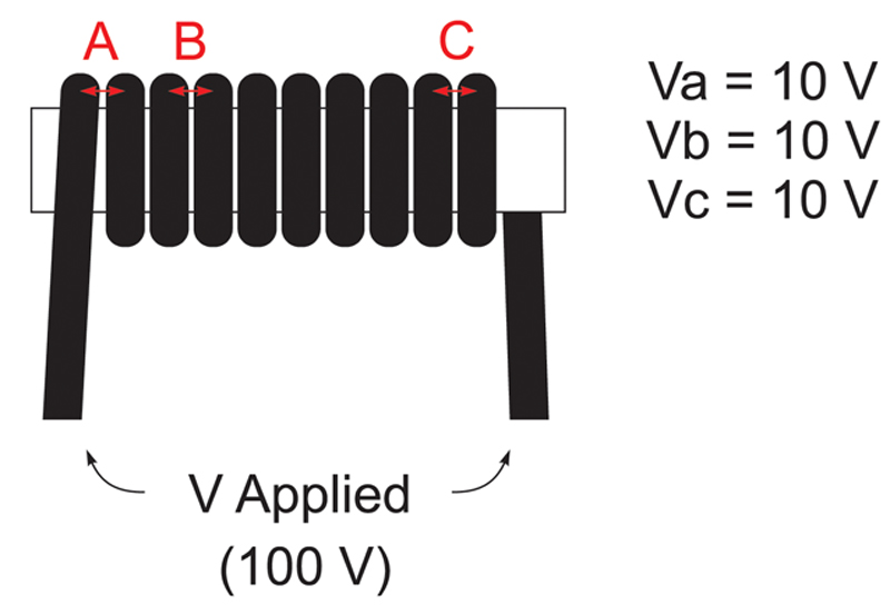
Figure 1: Voltage distributes equally across inductor turns
Yes, voltage ratings for inductors. The popularity of molded composite core inductors has placed new emphasis on voltage ratings to ensure safe and reliable inductor operation. Molded-core inductors place the core material in direct contact with the windings, changing the way inductor windings are insulated. New circuit trends like direct 48 V-to-core conversion and high-voltage battery stacks for electric vehicles, as well as device technologies like GaN and SiC switching transistors with fast transitions and higher voltage capability, can place increasing voltage stress on switching power supply inductors. All of this requires new care to be taken to ensure suitable inductors are chosen for each application. Clever designers have asked for operating (working) voltage ratings and inductor makers have responded. This article will discuss why these ratings are so important and what the circuit designer must consider.
Background
Mathematically, inductor performance can be described in terms of either voltage or current. Voltage relates mathematically to flux density of course, and current provides the electromotive force H. Inductor voltage drives di/dt, so while the stimulus may start as voltage, the ultimate impact of interest to the inductor is the result of induced current. Current cannot exist without voltage, nevertheless designers are accustomed to specifying inductor circuit operation almost exclusively in terms of current. Inductor specifications include temperature rise, core saturation, inductance change, core loss, winding loss and more, all of which result from current flowing in the inductor winding. All of this explains why designers are much more likely to have been thinking about current ratings when choosing inductors rather than a voltage rating.
Voltage Stress
Just as for all electronic devices, however, maximum voltage must be considered. Simply, voltage across the inductor terminals must not exceed the insulation capacity of the inductor. Too much voltage can damage the winding insulation and cause turn-turn short circuits, or even a short across the entire inductor. Inductor datasheets have not traditionally given a lot of guidance in this area, and yet until now this hasn’t caused much trouble for the vast majority of applications. This may simply be due to the fact that most high voltage applications call for relatively high inductance, and vice-versa. This is certainly true for dc-dc converters as L is chosen to set di/dt to a reasonable value. Whether it is a concern about saturation at the peak current or losses from peak-peak ripple, the choice of L is usually based on setting di/dt to the appropriate level. Roughly speaking, if an application calls for hundreds of volts across the inductor, L is usually hundreds of micro-Henries or more. For example, it would be an uncommon power converter to use a 1 uH inductor for a 500 V application.
Example 1
One may wonder what the inductance value has to do with voltage rating and insulation capability. The answer is inductor impedance is the series combination of the winding impedances, and since each turn has about the same impedance, any voltage across the inductor terminals divides evenly across inductor turns. The more turns an inductor has, the less voltage per turn. Since high L inductors have more turns than low L inductors, this natural relationship helps reduce voltage stress on inductor winding insulation in many practical applications. Consider how the voltage is distributed across the turns of the idealized inductor in figure 1.
If this 10-turn inductor is in a dc-dc converter with 100 V applied, we expect voltage across the insulation is only 10 volts at any point in the winding. For quality winding insulation in a traditional inductor style like this, 10 volts represents a very small, non-concerning level of stress on the insulation. This simple sharing of inductor voltage across winding turns has helped make voltage stress a low priority concern.
Example 2
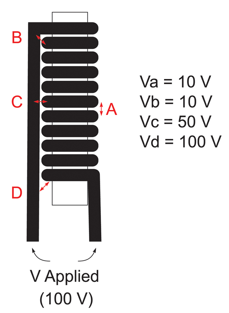
Consider the simple variation illustrated in figure 2 with the inductor reoriented to mount vertically on a pcb. The turn-turn voltage stress in our example is still only 10 volts between any two adjacent winding turns.
Click image to enlarge
Figure 2: Winding geometry can create unexpected areas of voltage stress
However, the placement of the long lead wire now creates a different level of voltage stress to each winding turn, with the maximum 100 V stress at point D. Inductor manufacturers have a long history of designing and building inductors in a wide variety of shapes and sizes, carefully choosing insulating materials and winding patterns to ensure a reliable performance and long lifetime. Nevertheless, this simple example demonstrates that addressing inductor voltage stress requires a careful look at inductor shapes and winding geometries.
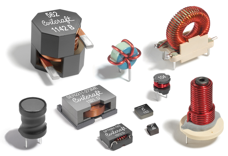
Of course, this doesn’t address the choice of different insulation material, nor does it begin to describe all possible inductor geometries (figure 3). Many, if not most, inductors are not built in such idealized shapes and the voltage sharing is more complicated.
Click image to enlarge
Figure 3: Inductors are made in a wide variety of shapes that can influence voltage stress
Molded Core Inductors
Molded-core inductors complicate the situation because the core material is in contact with the windings, filling all air gaps and intra-winding spaces throughout the inductor (figure 4). The molded core material is always a mixture of electrically insulating material and electrically conductive particles and, therefore, can impact the effective insulation level in the inductor, depending both on the material chosen and the winding geometry. The best material will provide the needed inductor parameters and yet maintain good voltage robustness.
Click image to enlarge
Figure 4: Inductor cross-section shows molded core material surrounds windings
Every inductor manufacturer has this same challenge: choosing the material and winding geometry that balance performance parameters like high saturation current and low core losses, as well as the need for high quality insulation to withstand expected voltage stress. However, each manufacturer must also choose material that is compatible with their manufacturing process. All of this gives new meaning to a phrase like “inductors may look alike, but they’re not all equal on the inside”. And since the user literally cannot look inside, responsibility falls to the manufacturer’s ratings to provide proper guidance.
Inductor Voltage Ratings
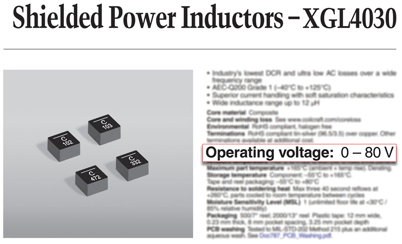
Traditional ferrite core inductors as shown in figures 1 and 2 have relatively high voltage capacity because the windings have little contact with the core, and ferrite cores have relatively high resistivity. It has been observed however, that some molded inductors might be degraded by operating voltage as low as 20 volts or less. With such low insulation capacity, inductor degradation could be caused by voltage in many applications and it is incumbent on the designer to carefully review inductor ratings, and particularly to consult the manufacturer about the use of any molded inductors that don’t carry such ratings on the datasheet. Inductor users should look to manufacturer datasheets for operating voltage, sometimes known as working voltage. Coilcraft has added Operating Voltage ratings to molded inductor datasheets, with most off-the-shelf families rated in the 60-80 volt range, and many sizes available in “V” versions for up to 120 volts.
Click image to enlarge
Figure 5: Operating voltage rating necessary for molded core inductors
Operating voltage is the maximum voltage between the terminals without insulation breakdown or any negative impact to either the performance or reliable operating life of the inductor. This should not be confused with dielectric withstand voltage, which is often a specification of transformers and other components and easily confirmed by hipot test. Since the operating voltage rating refers to voltage between the inductor terminals, it cannot be tested by means of a typical hipot test. Inductors have little to no impedance at low frequency, so a hipot test between inductor terminals would draw huge current, making a hipot test infeasible. As mentioned earlier, this is the same reason higher voltage applications generally use higher inductance values. Instead of hipot, operating voltage is confirmed by other testing methods developed specifically for inductor and motor windings such as surge testing. Surge testing energizes inductors to determine insulation integrity.
Conclusion
Molded core inductors are the best and most popular choice for many of today’s applications due to their combination of high current ratings, small size, rugged construction, and excellent magnetic shielding. Use of these inductors requires paying proper attention to inductor voltage ratings. While insulation integrity has always been a part of good inductor design, molded-core inductors place a new value on meaningful voltage specifications and proper communication with a reputable inductor manufacturer.