Why dimming?
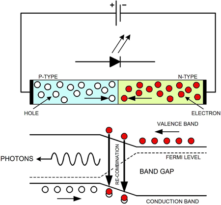
Light emitting diodes were first demonstrated by Nick Holnyak of General Electric in 1962. Over the following two decades the physics of LED illumination was understood sufficiently for LEDs to replace incandescent bulbs and vacuum tubes in indicators and numeric displays. In the early 1990s researchers at Hewlett-Packard, Toshiba and Nichia introduced high brightness red, green and blue LEDs. LEDs were starting to replace incandescent lamps in virtually all monochrome signaling applications, where their reliability and luminous efficacy, the ratio of light output to power input, is superior. A quick trip down the road will confirm this, most traffic lights, particularly new installations, use LEDs. In fact during the late 1990s luminous efficacy of LEDs has exceeded that of incandescent lamps and is approaching fluorescent lamps. LED action is shown in figure 1. The diode consists of an electron- carrying n-layer and a hole-carrying p-layer. When a forward voltage is applied to the structure (negative to the n-layer and positive to the p-layer), electrons injected from the n-layer radiatively recombine with holes emitting photons. The wavelength and colour of the photons is determined by the difference in the energy levels of the electrons and holes.
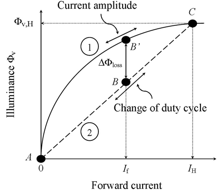
The requirement for dimming LEDs first emerged in small format liquid crystal display backlighting in cellular handsets. Once the mobile phone evolved from the simple voice-centric application to one carrying multimedia content, especially video, the power consumed by a display and its backlighting became significant. White backlighting from RGB mixing or phosphor down-converted blue LEDs was available albeit at too high a power consumption for extended viewing. At the same time large format LCDs replaced CRT monitors in personal computers. Energy efficiency standards, which apply to office equipment together with the elimination of hazardous substances such as mercury from cold cathode fluorescent lamps used for backlighting bought solid-state lighting specifically LEDs to the forefront of technology. As dimming of LED backlights in the handset and PC monitor became more sophisticated approaches to saving energy and enhancing display contrast were under investigation for LCD-TV. In fact content-adaptive brightness control of LCD-TV displays in which the video processor dynamically adjusts the brightness in zones of the display according to the video content in real-time is commonplace. This is by far the most demanding of dimming applications requiring precision timing and LED current control without interfering with the video signal or causing visible artifacts such as display shimmering, which is caused by intermodulation or beating between the video and harmonics of the dimming control signal. Visual display applications require the most sophisticated dimming solutions and are constantly under review with the aim of saving energy. It is with energy efficiency in mind that general lighting applications require dimming. For example in the newest generation of "smart buildings" the lighting is zoned so that artificial lighting at the periphery of the building next to windows is minimal during daylight hours. Luminaires are networked in such installations so that sensors deployed at certain points can keep the ambient light level constant or switch off zones altogether when passive infrared occupancy detectors signal that nobody is present in the area. Dimming is also used as part of RGB mixing to create lighting which enhances the subject. For example supermarkets use fluorescent lamps with a phosphor that emits a spectrum of light, which makes meat or vegetables look more appealing. RGB LEDs can be mixed for a particular spectral output with additional energy savings and higher reliability. LEDs may be driven with a direct current (amplitude mode) or with a pulsating current (PWM) or by a hybrid technique. At first inspection it seems simple to operate the LEDs with dc. However the device's low dynamic resistance gives it a high sensitivity of forward current to a change in forward voltage. Additionally it has been found that a direct change of forward current can alter the emitted wavelength of the LED at different intensities. In contrast dimming may be achieved by pulse width modulation, which controls the pulse duration rather than current amplitude yielding improved colour stability. This stability is gained by sacrificing luminous efficacy as the LEDs have to operate at higher current amplitude during the forward current pulse for the same average current as the dc current case. The luminous output of LEDs has a tendency to saturate at higher forward currents. Figure 2 illustrates the two techniques for driving and dimming LEDs. Line 1 shows the non-linear luminous output from an LED driven by direct-current. Line 2 shows the same LED driven with a pulse width modulated for red current. For a particular average forward current it is shown that PWM drive results in a loss in luminous output DFloss. The reason for this disparity is that the LED is operated at a point of lower luminous efficacy IH. The hybrid case, which is a mix of the direct current and PWM techniques, is the best of both worlds. The only drawback of the hybrid approach is that the dimming range may be reduced.
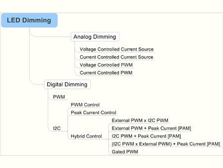
The mSilica approach to LED dimming, illustrated in figure 3, is sophisticated and comprehensive. This is not surprising; these techniques were developed in anticipation of the most demanding LCD-TV backlighting requirements. Electromagnetic compatibility and energy efficiency are prime considerations for LCD-TV design along with the requirement for contrast ratios in excess of 50,000:1. Furthermore, this needs to be achieved in such a way that the driver is scalable for large format LCDs and independent of power source technology so that the drive scheme readily adapts to the customers' system implementation. Energy efficiency is assured via a closed loop system which modulates the dc voltage applied to the strings in order to set the voltage across the current source MOSFET at its optimum point for a particular string current. Consequently the energy consumed by the backlight is no more than that needed for optimum performance in real-time regardless of the operating point. In the case of RGB drivers three independent power optimization loops are used. Two top-level categories of LED dimming analog dimming and digital dimming are available. Analog dimming is achieved using a variable dc voltage or current which sets the LED string current source. Alternatively that dc voltage or current may be compared with a sawtooth waveform at a PWM comparator that generates a PWM signal, which programs the average LED string current. Digital dimming may be further subdivided into PWM or I2C categories depending on the interface. The PWM input may come from a simple oscillator with a variable mark-space ratio or a microcontroller. The I2C signal may come from the microcontroller or the graphics interface depending on the sophistication of the solution. In each case there are a variety of options available depending on the dimming range (or contrast ratio) desired. Coupled with the high contrast ratio is the requirement for low noise and minimal interaction with video signals or sensitive circuitry. Low electromagnetic interference is achieved by synchronization, phase shifting and sequencing of pulsating string currents and programming signals such that low frequency ripple on the string supply is minimized and fast edges, or the harmonics thereof, do not interfere with video signals.
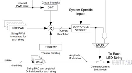
The PWM engine at the heart of the mSilica LED driver range is shown in figure 4. The register ISTRn sets the peak LED string current with 4 to 8-bit resolution. The DACn output controls the string current sinks. The current demand signal is switched by the output of the multiplexer MUX. If there is no phase delay or internally generated PWM signal the external PWM input modulates the current in the strings directly. If the internal duty cycle generator is active, string duty cycle, which is stored in a register STRnPWM with 12-bit resolution, sets the output. This drive may be modified by an 8-bit global intensity register, GINT that reduces the duty cycle for all strings or by a thermal derating factor, SYSTEMP. System-specific input to mark-space ratio and clock synchronization occurs in the DUTY CYCLE Generator. The mSilica PWM engine makes all the modes shown in figure 3 possible, without compromising efficiency, precision, signal to noise ratio or performance over temperature range.
LED dimming is not as simple as it seems. There is a bewildering array of options available ranging from dc or PWM current control to complex hybrid techniques, which offer unparalleled contrast ratio to the LCD-TV designer without compromising on overall system performance. All these options integrate seamlessly with the chosen power supply topology. The products of this harsh proving ground for LED dimming circuits are now available for general illumination applications. The highest contrast ratio methods may be excessive. However, RGB mixing and energy optimization are equally applicable wherever similar standards apply. www.msilica.com