LED Lighting Circuit Protection Strategies

Improving reliability and lifespan
As government agencies, industry and consumers look for ways to reduce energy costs, light-emitting diode (LED) lighting technology is expected to boom. LED technology has advanced rapidly, with improved chip designs and materials facilitating development of brighter and longer-lasting light sources that can be used in a wide spectrum of applications. Today, LED lights are quickly replacing conventional lighting based on the following advantages:
- Low energy consumption - retrofit bulbs range from 0.83 to 7.3 Watts
- Long service life - LED bulbs can last up to 50,000 hours
- Durable - LED bulbs are resistant to thermal and vibrational shocks and turn on instantly, making them ideal for applications that are subject to frequent on-off cycling
- Help meet safety and green initiatives - LEDs remain cool to the touch and contain no mercury
- Fully dimmable - LEDs do not change color when dimmed, unlike incandescent lamps that turn yellow
- No frequency interference - no ballast to interfere with radio and television signals
In spite of the growing popularity of the technology, LED light manufacturers are challenged by the fact that LED luminaires are very heat sensitive; specifically, excessive heat or inappropriate applications can dramatically affect their performance. LED luminaires require precise power and heat-management systems, since most of the electrical energy supplied to an LED is converted to heat rather than light. Without adequate thermal management, this heat can degrade the LED's lifespan and affect color output. Also, because LED drivers are silicon devices they can fail short. This means fail-safe backup overcurrent protection may be required. Power line coupled transients and surges can also reduce LED lifespan and many LED drivers are susceptible to damage resulting from improper DC voltage levels and polarity. LED driver outputs may also be damaged or destroyed by short circuits. Most LED drivers include built-in safety features, including thermal shutdown, as well as open and short LED detection. However, additional overcurrent protection devices may be needed to help protect integrated circuits (ICs) and other sensitive electronic components. Resettable polymeric positive temperature coefficient (PPTC) circuit protection devices have demonstrated their effectiveness in a variety of LED lighting applications. Like traditional fuses, they limit current after specified limits are exceeded. However, unlike fuses, PPTC devices have the ability to reset after the fault is cleared and the power is cycled. A variety of overvoltage protection devices including metal oxide varistors (MOVs), electrostatic discharge (ESD) surge protection devices, and integrated overcurrent/overvoltage devices can be used in a coordinated scheme with PPTC devices to help improve LED performance and reliability.
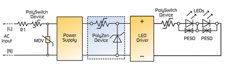
LEDs are driven with a constant current, with the forward voltage varying from less than 2V to 4.5V, depending on the color and current. Older designs relied on simple resistors to limit LED drive current, but designing an LED circuit based on the typical forward voltage drop as specified by a manufacturer can lead to overheating of the LED driver. Overheating may occur when the forward voltage drop across the LED decreases to a value significantly less than the typical stated value. During such an event, the increased voltage across the LED driver can result in higher total power dissipation from the driver package. Today, most LED applications utilize power conversion and control devices to interface with various power sources, such as the AC line, a solar panel or battery power, to control power dissipation from the LED driver. Protecting these interfaces from overcurrent and overtemperature damage is frequently accomplished with resettable PPTC devices. The PPTC device has a low-resistance value under normal operating currents. In the event of an overcurrent condition, the device "trips" into a high-resistance state. This increased resistance helps protect the equipment in the circuit by reducing the amount of current that can flow under the fault condition to a low, steady-state level. The device remains in its latched position until the fault is cleared. Once power to the circuit is cycled, the PPTC device resets and allows current flow to resume, restoring the circuit to normal operation. While PPTC devices cannot prevent a fault from occurring, they respond quickly, limiting current to a safe level to help prevent collateral damage to downstream components. Additionally, the small form factor of PPTC devices makes them easy to use in space-constrained applications. Figure 1 illustrates a coordinated protection scheme for switch-mode power supplies (SMPSs) and LED driver inputs and outputs. As shown on the left-hand side of the figure, a PPTC device, such as a PolySwitch™ device, can be installed in series with the power input to help protect against damage resulting from electrical shorts, overloaded circuits or customer misuse. Additionally, an MOV placed across the input helps provide overvoltage protection in the LED module. The PPTC device may also be placed after the MOV. Many equipment manufacturers prefer protection circuits combining resettable PPTC devices with upstream fail-safe protection. In this example, R1 is a ballast resistor used in combination with the protection circuit. LED drivers may be susceptible to damage resulting from improper DC voltage levels and polarity. Outputs may also be damaged or destroyed by an inadvertent short circuit. Powered ports are also susceptible to damaging overvoltage transients, including ESD pulses. The right side of Figure 3 shows a coordinated circuit protection design for an LED driver and bulb array. A PolyZen™ device placed on the driver input offers designers the simplicity of a traditional clamping diode while obviating the need for significant heat sinking. Developed by Tyco Electronics, this device's unique polymer-protected precision Zener design helps provide transient suppression, reverse bias protection and overcurrent protection in a single, compact package. As shown in Figure 3, a PolySwitch PPTC device on the driver output can help protect against damage caused by inadvertent short circuits or other load anomalies. To fully leverage the PolySwitch device, it can be thermally bonded to the metal core circuit board or LED heat sink. To help prevent damage caused by an electrostatic discharge (ESD) event, ESD protection devices, such as low-capacitance (typically 0.25 pF), small-form-factor PESD devices can be placed in parallel with the LEDs.
MOVs are typically used for transient overvoltage suppression in AC line-voltage applications. New thermally-enhanced MOVs help protect a wide variety of low-power systems against damage caused by overcurrent, overtemperature and overvoltage faults, including lightning strikes, ESD surges, loss of neutral, incorrect input voltage and power induction. Figure 2 shows how Tyco Electronics' 2Pro™ device helps provide protection for AC mains LED lighting systems.
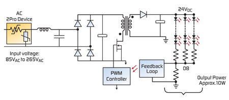
Under normal operating conditions the AC line voltage applied to an MOV is not expected to exceed the device's maximum AC root mean voltage (VAC RMS) rating and, provided that the transient energy does not exceed the MOV's maximum rating, short-duration transient events are clamped to a suitable voltage level. However, a sustained abnormal overvoltage/limited current condition, such as a loss of neutral, may cause the MOV to go into thermal runaway. The 2Pro device combines PPTC technology with an MOV component into one thermally protected device to help provide resettability in case of overcurrent or overvoltage events. This integrated-device approach was developed to help manufacturers meet industry requirements, such as IEC61000-4-5 and IEC60950.
A coordinated circuit protection scheme can help LED lighting designers reduce component count, provide a safe and reliable product, comply with regulatory agency requirements, and reduce warranty and repair costs. As with any circuit protection scheme, the effectiveness of a solution will depend on the individual layout, board type, specific components, and unique design considerations. Tyco Electronics works with OEM customers to help identify and implement the best approach. www.circuitprotection.com