Author:
Yangyang Wen & Nazzareno (Reno) Rossetti, Maxim Integrated
Date
06/01/2020
 PDF
PDF

Click image to enlarge
Figure 1. Industrial Security Camera in Action.
Demand for industrial video surveillance equipment (Figure 1) is rapidly growing. Businesses benefit from using video systems that provide higher security for customers and employees. They help detect theft and monitor employees to make sure they are complying with safety guidelines. A new growth area for video surveillance are embedded vision systems, including augmented reality as well as advanced behavior, face, gesture and object recognition. The migration from analog to digital Power-over-Ethernet (PoE) network surveillance cameras enables scalability and increases capabilities for video surveillance systems. In a typical PoE network, a set of IP cameras converges on a network video recorder (NVR), which connects to a router for internet access. PoE switches can then be added to the network to accommodate more cameras. But the deployment of multiple cameras creates issues with power dissipation that need to be addressed. In this design solution, we will discuss how a powered device (PD) for PoE applications achieves higher system efficiency thanks to a host of operating modes with increased power reduction.
PoE
Power-over-Ethernet (PoE) refers to the technology of relaying electrical power over an Ethernet cable which was, conventionally, intended to transmit only data. Via the IEEE 802.3af/at standard, the power sourcing equipment (PSE) can transmit up to 30W of power to the downstream power receiver (referred to as a ‘powered device’ or PD) while supporting a 1000-BASE-T data flow. In 2017, the IEEE802.3bt standard was formulated to develop a more autonomous, capable, and efficient PoE framework which allows a 10G-BASE-T data transfer with power delivery up to 90W. This article will discuss how to generate additional power savings using an IEEE 802.3af/at/bt-compliant PD.
Maintain Power Signature (MPS)
Even when an individual PD is operating at minimum load, it still consumes operational power. Such power, when added across the entire PoE system for all PDs, adds up to a significant amount of standby power and reduces the efficiency of the entire application. For example, a PD port of 48V that consumes 30mA current is close to 1.5W power consumption. To keep a thorough accountability for such power loss at a low load, the IEEE standard has defined the Maintain Power Signature (MPS) scheme.
To avoid disconnection from the PSE, a PD should maintain a certain level of average current for certain on-time and off-time, which is defined in IEEE 802.3af/at/3bt.
Application Circuit of an Example Powered Device
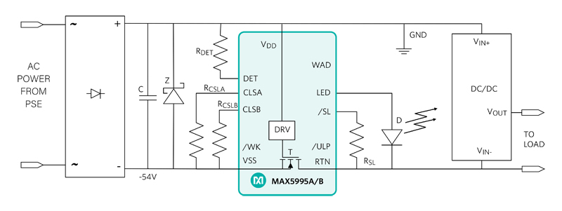
Figure 2 shows a typical application circuit for the MAX5995 PD. We will use this PD to show how to save power for POE applications. The incoming power from the PSE is supplied to this device across VDD and VSS and the output power is delivered across VDD and RTN. A wall adapter power could be connected across WAD and RTN to source power locally.
The device features a dedicated LED pin which can be programmed to source out DC current when the device is in MPS, sleep, or Ultra-Low-Power sleep modes (these modes are discussed in detail later). The magnitude of the LED current can be controlled as per the value of the RSL resistor connected to the /SL pin. Driving the /SL pin allows entry into sleep mode. Driving the /ULP pin low and then pulling the /SL pin low allows entry into ultra-sleep mode. The /WK pin is used to exit any of the sleep and Ultra-Low-Power sleep modes. A resistor (RDET = 24.9kΩ) from DET to VDD implements the single-signature PD detection. Two external resistors, RCLSA/ RCLSB, connected from CLSA/CLSB to VSS set classification signature to the PSE and define the power consumption requested from the PD.
Click image to enlarge
Figure 2. Application Circuit for the MAX5995B
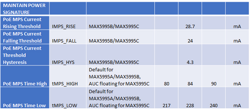
Table 1 shows the specifications that pertain to the MPS feature where the minimum current applies to the Intelligent MPS feature. This is defined as 24mA (IMPS_FALL) and the maximum threshold to exit the mode is 28.7mA (IMPS_RISE). The high and low times for the MPS signature are defined as tMPS_HIGH and tMPS_LOW, respectively. Do note that the tMPS_HIGH/tMPS_LOW = 84ms/228ms ~27% duty cycle, typically. Also, when the device is in MPS mode, the sleep or Ultra-Low-Power sleep modes cannot be activated.
Click image to enlarge
Table 1. MPS Feature Specifications for MAX5995B
This device includes the Intelligent MPS feature, which modulates the input current with a 27% duty cycle (312ms typical time period) when the input current is less than a typical threshold of around 24mA. Such a scheme helps achieve the following benefits:
· By modulating the current as per a specific pattern, the MAX5995B reduces the average DC current lower than 10mA, reducing power consumption.
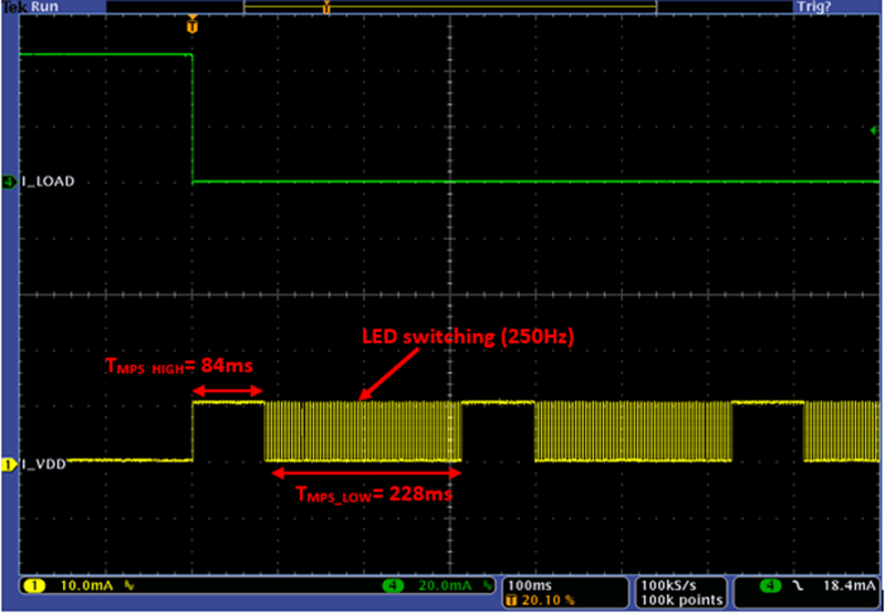
· At extremely low-load currents (or at no load), the Intelligent MPS feature of MAX5995B ensures that the average DC current is maintained just enough to prevent a total disconnection from the PSE. As can be seen in Figure 3, the MAX5995B realizes this by maintaining a non-pulsating DC current for 84ms duration over the total period of 312ms.
The LED driver supported by the MAX5995B sources periodic current pulses at 250Hz (amplitude programmed by the resistor between the /SL and VSS pins) when the device enters into sleep or Ultra-Low-Power sleep mode. Internal to the IC, both the Ultra-Low-Power sleep and the MPS modes utilize the same electrical circuit resulting in 250Hz pulsation in MPS waveform during its low period. Figure 3 shows the device entering the MPS mode when the load current (I_LOAD) is reduced such that the input current falls below the MPS threshold. The current into the VDD pin is observed to start generating the MPS pattern, and the LED current waveform is seen during the low period of the MPS. Note that the load is connected in between VDD and RTN. The current into the VDD pin is not a reflection of the load current.
Click image to enlarge
Figure 3. The MAX5995B entering MPS mode at low operational current
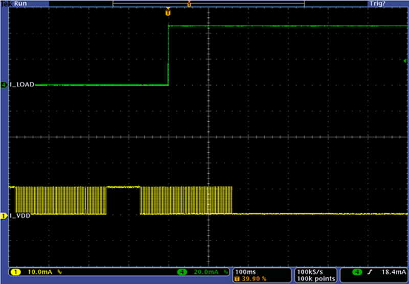
Figure 4 shows that when the load current increases above the IMPS_RISE threshold, the MPS mode switches off and the VDD current no longer demonstrates the pattern.
Click image to enlarge
Figure 4. The MAX5995B exiting MPS mode when operational current exceeds the MPS threshold.
Sleep and Ultra-Low-Power Sleep Modes Save Power
The sleep mode and Ultra-Low-Power sleep mode in the MAX5995A/B allow the PD system to further reduce power consumption by pulling PG low to disable downstream DC-DC converters, while still maintaining MPS current and PSE connection. These power-saving modes could be triggered by some external application-driven criteria or simply be used to turn off the system during idle operation.
Sleep Mode
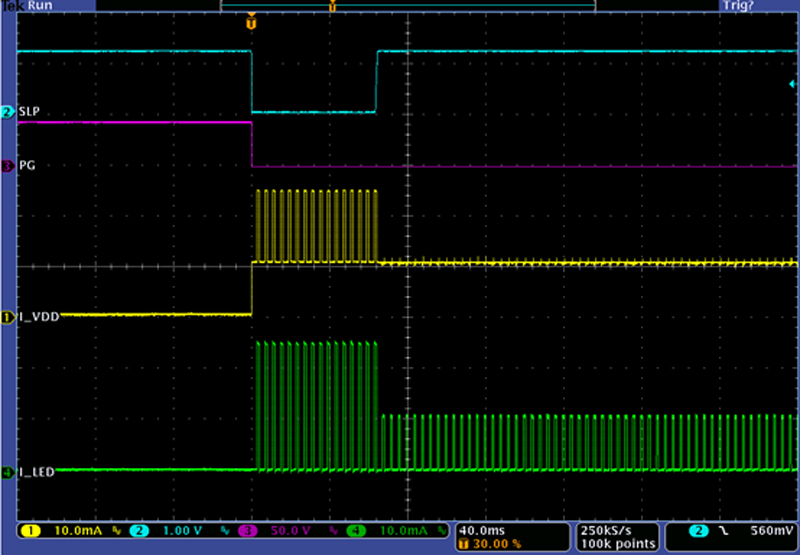
The sleep mode can be entered on the device by driving the /SL pin low. Once in sleep mode, the device de-asserts the power-good (PG) pin, which could eventually disable the DC-DC converter output. Upon entering sleep mode, the LED pin begins sourcing current as per the RSL resistor connected at the /SL pin. The device maintains input current to a minimum DC level that is sufficient to prevent disconnection from the PSE. Figure 5 shows waveforms demonstrating this behavior.
Click image to enlarge
Figure 5. Entering sleep mode on the MAX5995B.
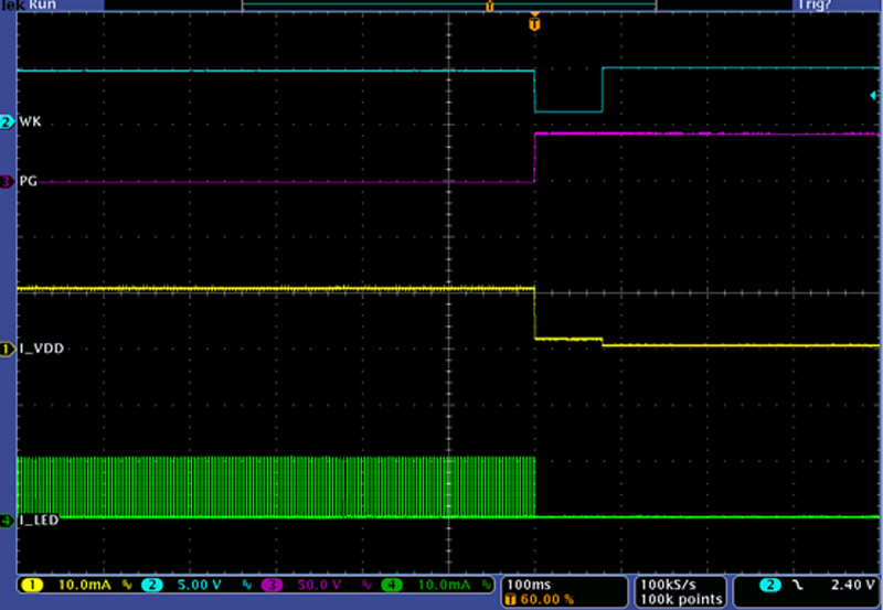
Pulling down the open-drain input /WK pin commands the device to exit sleep mode and re-enables the DC-DC converter output. Also, the LED current is turned off upon exiting the mode. Figure 6 demonstrates the waveforms that appear when exiting sleep mode.
Click image to enlarge
Figure 6. Exiting sleep mode on the MAX5995B.
Ultra-Low-Power Sleep Mode
Besides sleep mode, the MAX5995B also supports Ultra-Low-Power sleep mode, which further reduces power. Like sleep mode, the Ultra-Low-Power sleep mode de-asserts the PG pin and the LED pin sources out constant current as per the connected RSL resistor. In addition, the Ultra-Low-Power sleep mode activates the MPS feature to modulate the input current and reduces power consumption more than the sleep mode.
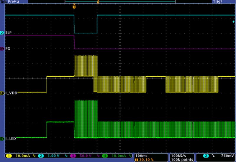
To enter the Ultra-Low-Power sleep mode, the /SL pin needs to be pulled low with the /ULP pin already pulled low. Figure 7 shows the MAX5995B entering Ultra-Low-Power sleep mode. The VDD input current waveform shows the MPS pattern.
Click image to enlarge
Figure 7. Entering Ultra-Low-Power sleep mode on the MAX5995B.
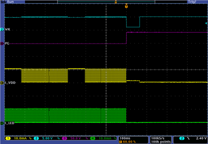
To exit Ultra-Low-Power sleep mode, pull down the /WK pin, as shown in Figure 8.
Click image to enlarge
Figure 8. Exiting Ultra-Low-Power sleep mode on the MAX5995B
When the device is in MPS mode, sleep and ultra-sleep modes cannot be activated.
Conclusion
Power-saving modes can greatly reduce power consumption and improve power efficiency for the entire PoE system when multiple PD devices are operating. The MAX5995B is an IEEE 802.3bt PD for PoE applications and hosts power reduction modes to achieve higher system efficiency. Through the features such as Intelligent MPS, the MAX5995B achieves power-saving mode at low-load conditions while still remaining connected to the PSE. This feature helps improve the overall efficiency of the entire PoE system.
The sleep and Ultra-Low-Power sleep features on the MAX5995B allow it to be activated by the system master with dedicated /SL and /ULP pins. This further reduces the power consumption in the PoE system. Through the sleep mode of MAX5995B, the device can be commanded to turn off the active load connected to the PD. The Ultra-Low-Power sleep mode is used to attain the features of sleep mode while conserving more power by operating in MPS mode.