High efficiency, longer life and lower maintenance
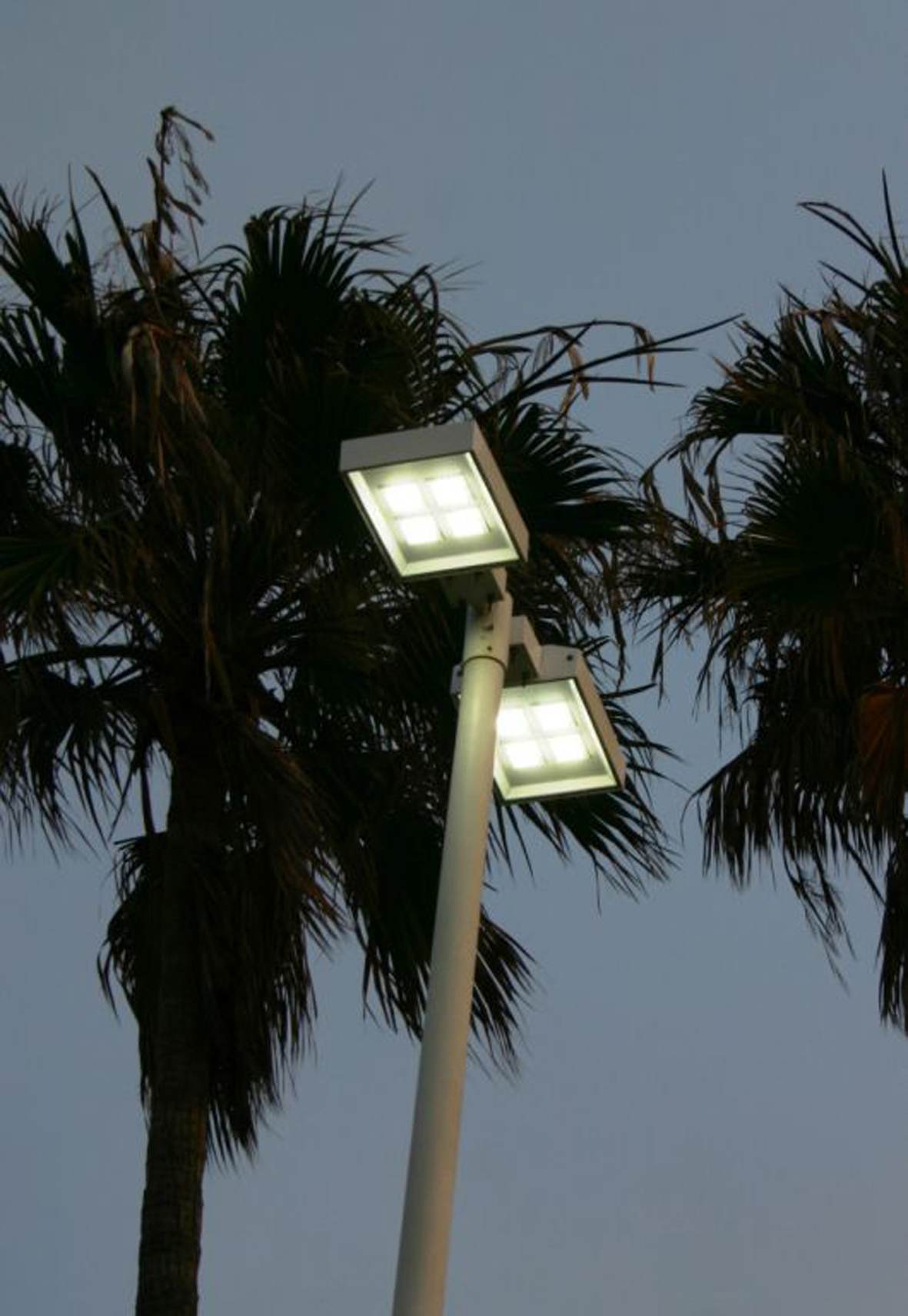
Figure 1: LED street lights
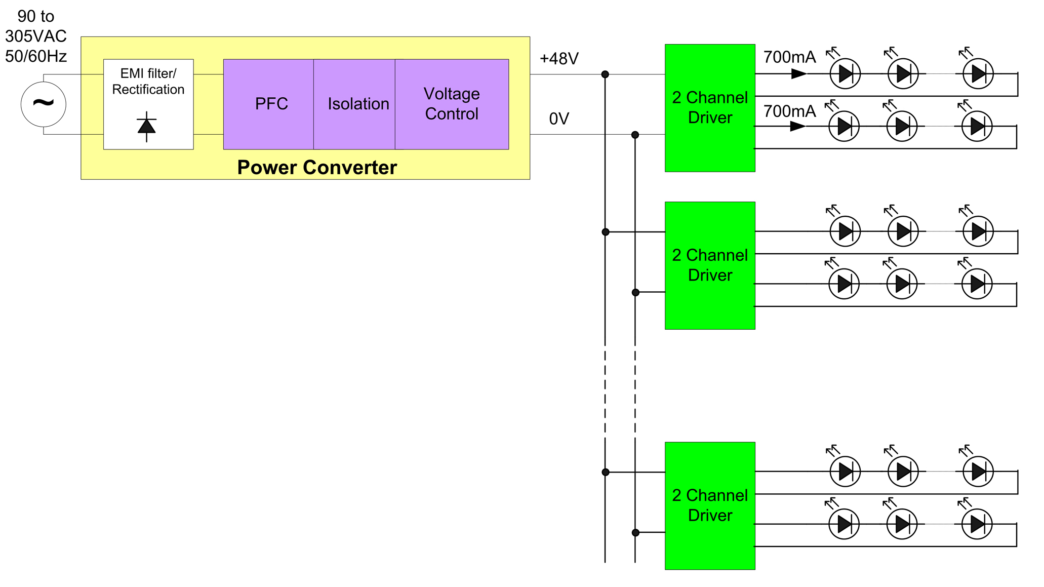
High brightness LED street lights are now being installed in pilot projects at many sites. In most cases these are replacing high intensity discharge (HID) and high pressure sodium (HPS) street lamps. Although HID lamps have long operating life and high luminous efficacy, well designed LED based systems offer the advantage of directing the light in a downward cone providing high illumination at ground level without radiating much of the light sideways. The operating life of well designed LED systems using adequately rated components with sufficient heat sinking can be as much as double that of HID lamps reaching 50000 hours. LED based systems have the added advantage of controllability and can be dimmed over a wide range unlike HID lamps, which can only be dimmed to about 50%. HID lamps require a high voltage pulse to ignite the lamp. This is typically 1 to 4kV for a cold lamp but increases to over 20kV for a hot lamp, making most HID lamp ballasts unable to provide a hot re-strike. The lamp therefore needs to cool for several minutes before it can be switched on. LED based street lamps typically consume 120 to 200W of power whereas HID systems require 300 to 400W. The lumen levels however are comparable when measured at ground level not because the LED light source has a greater Lumen per Watt output than HID but because LED optics enable the light to be directed where required. Switching power supplies for the power levels needed for LED street lighting are usually based on a different circuit topology to lower power LED drivers. Flyback converters although well suited to power supplies below 50W are bulky and inefficient at 100W and above, therefore a multi stage design is normally used instead. In this type of power supply, the front end consists of a power factor correcting Boost regulator providing a high voltage DC bus. Active power factor correction (PFC) circuitry of this kind is widely used in power supplies and electronic ballasts although there is some penalty in efficiency. The PFC stage typically has above 90% efficiency which increases as higher power levels. The PFC stage is followed by an isolating step down back end stage designed to produce a regulated current output. This stage could be a single or two switch Flyback converter, Forward converter or half bridge resonant converter. In some LED street light designs a modular approach is used where the LED panel consists of several smaller panels connected separately to the LED power supply (or driver). Each LED module is driven by a constant current driver. In this type of system the main power supply produces an isolated fixed voltage typically 24 or 48V, low enough to fall within UL safety limits. The output channels to each LED module are then driven by current regulators all supplied from the central isolated low voltage bus. This is described as a multi channel LED driver.
Although modular systems offer convenience and the ability to build light fixtures of different shapes and sizes without the need for many differently rated power supply models, this approach is less efficient than a power supply with a single output. This type of power supply would drive a single panel containing and array of LEDs designed to operate at a fixed current. A typical example might operate at 1.4A with four parallel strings of 350mA LEDs matched so that the forward voltage for each string is very close. The power supply would be optimized for this output voltage and current and regulation could be provided by pulse width modulation (PWM) in the back end stage eliminating the need for additional output current regulators. This allows greater efficiency but less flexibility. The PFC stage Boost regulator typically operates in critical conduction (or transition) mode between discontinuous and continuous modes, meaning that the switching cycle begins as soon as all of the energy from the inductor has been transferred to the output. Many simple stand alone PFC control ICs are available the operate on this principle, however more complex dedicated ICs able to control this stage as well as the resonant half bridge or Flyback stage are now coming onto the market. The PFC stage provides a regulated high voltage DC bus over a wide range of input voltage and load enabling the LED power supply to operate with high power factor and low THD over a wide range of AC line input voltages (typically 90 to 305VAC), which covers most locations. The second stage is then greatly simplified since its transformer and power semiconductor components can be optimized for a fixed input voltage. The resonant half bridge is well suited for the second stage of the LED power supply. Unlike the Flyback converter it transfers power through the transformer continuously instead of periodically storing and transferring energy. This allows the transformer to be significantly smaller than the air gapped coupled inductor used by the Flyback. The Flyback is also prone to losses due to leakage inductance where the resonant half bridge uses the leakage inductance to enable commutation allowing zero voltage switching (ZVS) of the MOSFETs. Since the throughput power is controlled by modulating frequency instead of pulse width the dead time remains fixed allowing ZVS operating across the entire operating range. With no switching losses the efficiency can exceed 90%. Forward converters also offer smaller transformer size but an additional output filter inductor is needed and this type of circuit does not provide zero voltage switching. In both modular and single output systems with the output voltage being low the current must inevitably be high, for example at 48V output the current would be about 2A to supply a 100W LED load. The rectifying diodes even if they are Schottky types dissipate more than one Watt each. This can be reduced to negligible levels by replacing these diodes with MOSFETs driven by a synchronous rectifier control IC.
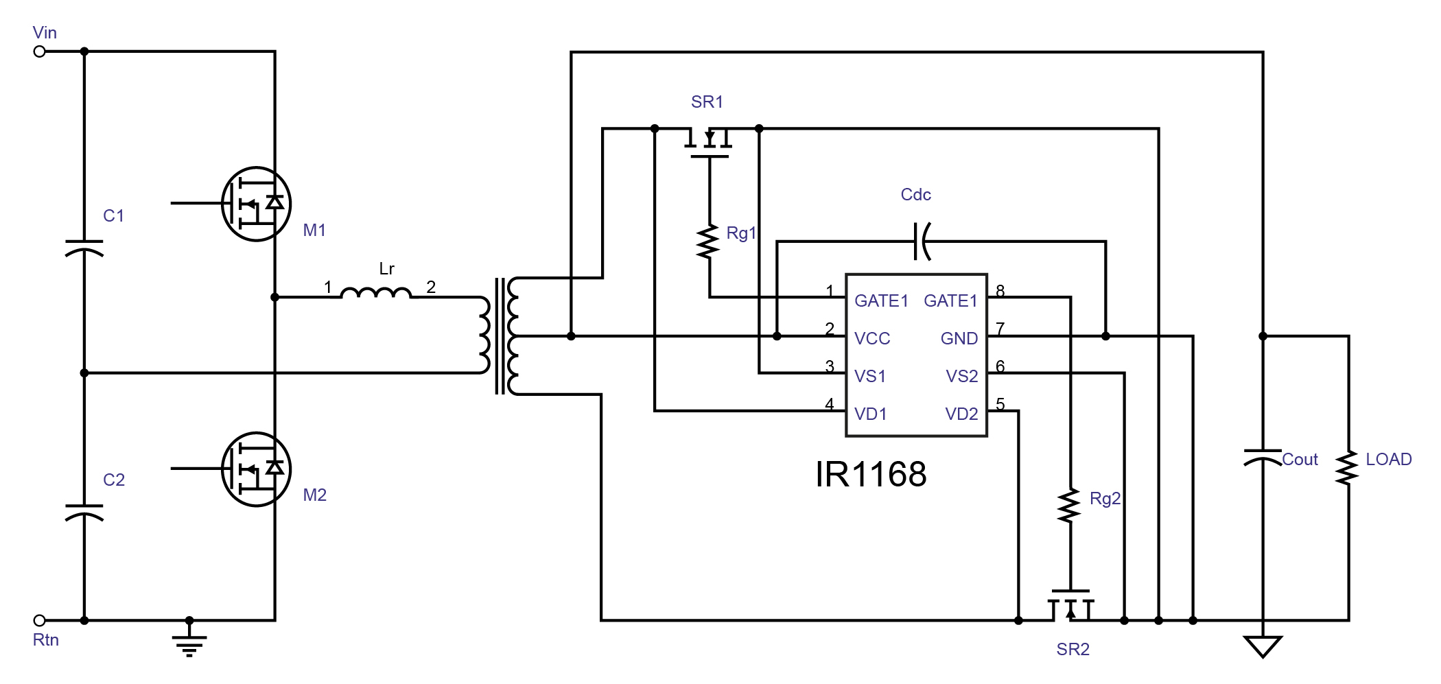
The circuit shown in figure 3 illustrates the resonant half bridge with the step down transformer and a synchronous rectification stage at the secondary to supply the load. Unlike LED replacement lighting for domestic use, a street lighting system does not need to be dimmable from triac based dimmers but the light output level does need to be adjustable to enable smart functionality such as the adjustment of light levels at different times during the night to optimize energy savings. The control method used might be a form of wired digital control like DALI or analog control through a 0-10V control interface widely used in lighting. Wi-Fi based control is also possible. In each case the light output is most easily adjusted by pulsing the output on and off at a frequency above the visible flicker level which is about 120Hz and varying the duty cycle. PWM dimming is well suited to this type of LED power supply since the half bridge drive and PFC can be pulsed on and off at varying duty cycles to provide smooth and flicker free light level adjustment. www.irf.com