New technology focuses on emerging applications
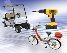
Technological advances in lithium ion (Li-ion) batteries have enabled high-power Li-ion cells with higher energy density and lighter weight to replace Nickel-Cadmium (NiCd) batteries - and even lead acid batteries - in applications such as power tools, e-bikes, light electric vehicles (LEVs) and back-up power supplies. Li-ion technology is more environmentally friendly than the NiCd or lead acid technologies; however, the challenge for the adoption of Li-ion batteries by these new markets is the greater emphasis by system designers on battery safety requirements compared with NiCd or lead acid technologies. A new approach to Li-ion battery pack circuit protection confronts these market challenges by offering an alternative to conventional higher-cost, space-consuming protection technologies. This new hybrid technology connects a bimetal protector in parallel with a PPTC (polymeric positive temperature coefficient) device. The resulting Metal Hybrid PPTC (MHP) device helps provide resettable overcurrent protection in high-rate-discharge battery packs while also utilizing the low resistance of the PPTC device to help prevent arcing in the bimetal protector at higher currents and by heating the bimetal to keep it open and in a latched position. The initial device introduced, the MHP30-36 device, has a 36VDC/100A maximum rating and a hold current of 30A. However, MHP device technology can be configured for various applications and higher voltage (up to 400VDC) and hold current (60A) devices are currently in development. The conventional approach Many of the conventional circuit protection techniques for high-rate-discharge Li-ion applications tend to be large, complex or expensive. Some circuit protection design approaches might use a combination of ICs and MOSFETs or similar complex solutions. Other designs might consider a conventional bimetal protector in DC power applications requiring 30A+ hold current, but the contacts must be large enough to handle the high current, resulting in an overall device size that is much larger. Additionally, the number of switching cycles must be limited due to contact damage that may result from arcing between the contacts. In comparison the new MHP hybrid device can replace or help reduce the number of discharge FETs and accompanying heat sinks used in some complex IC/FET battery protection designs. The MHP device offers space-reduction, cost-reduction and protection-enhancement benefits for high-rate-discharge Li-ion battery pack applications. How it works During normal operation, current passes through the bimetal contact due to its low contact resistance. When an abnormal event occurs, such as a power tool rotor lock, higher current is generated in the circuit causing the bimetal contact to open and its contact resistance to increase. At this point, the current shunts to the lower resistance PPTC device and helps prevent arcing between the contacts while also heating the bimetal, keeping it open and in a latched position.

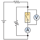
As shown in Figure 1, the activation steps of the MHP device include: 1. During normal operation, because contact resistance is very low, most of the current goes through the bimetal. 2. When the contact begins to open, contact resistance increases quickly. If the contact resistance is higher than the PPTC device's resistance most of current goes to the PPTC device and no — or less — current remains on the contact, therefore preventing arcing between the contacts. When current shunts to the PPTC device, its resistance rapidly increases to a level much higher than the contact resistance and the PPTC heats up. 3. After the contact opens, the PPTC device starts to heat up the bimetal and keeps it open until the overcurrent event ends or the power is turned off. A PPTC device's resistance is much lower than that of a ceramic PTC. This means that even when the contact opens just a small amount the contact resistance increases only slightly and the current can be shunted to the PPTC device and help prevent arcing on the contacts. Typically, the resistance difference at room temperature between ceramic and polymer PTC devices is in the range of two decades (x10^2); so when the higher resistance ceramic PTC devices are combined in parallel with a bimetal they are less effective than the MHP device at suppressing arcs at higher currents. Figure 2 shows a circuit diagram of the bimetal protector and PPTC device in parallel.
Smaller contact size and lower resistance On a typical bimetal protector the contact is located in only one place so it may exhibit weak voltage-withstand characteristics. Because higher currents would require a much larger form factor in a single contact design, the MHP device uses a type of contact that is referred to as "double-make" or "double-break" design in order to downsize the device (Figure 3). This technology offers several advantages as compared to a typical bimetal protector: 1. The device exhibits very low resistance because the current path is very short; 2. heat is only generated at the contact point, permitting the use of thermal control to achieve precise thermal activation; and 3. It enables MHP devices to have a smaller form factor compared to other breaker devices with a similar rating.
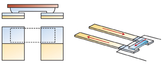
In comparison, with a standard bimetal contacts, the contact is located in only one place so it generally has weaker voltage withstand characteristics than the MHP device. Impact/Shock withstand improvement A specific advantage of the MHP device is that it can be used in the harsh operating environments of high-current applications by providing longer cycle life and high vibration/shock withstand. A typical power tool battery pack operates under severe vibration and impact conditions. To meet these requirements, the MHP device needs sufficient contact pressure between the contacts. Standard protector devices typically use an arm with strong spring tension to keep the movable contact on the fixed contact. But the spring tension is usually insufficient to maintain contact pressure under strong impact or vibration conditions — even if a strong spring is used. To overcome this challenge, design efforts for the MHP device focused on the bimetal disc, since a formed bimetal disc has sufficient strength to stay flat when there is no heat or thermal contact. In addition, a "hook" was added to the movable arm to enhance the contact pressure provided by the bimetal disc. The movable arm is a cantilever held by a pin located on the other side of the device. When a hook is added close to the contact, the movable arm rotation is reduced, resulting in a robust downward force on the two contacts. The initial MHP device for power tool battery applications is rated to survive at least 500 cycles and survive a 1500g drop test without failure, and as many as three cycles at 3000g.
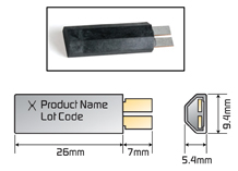
The first device available in a planned family of MHP devices, the MHP30-36-T device, has a 36VDC /100A maximum rating and a time-to-trip of less than five seconds at 100A (@25°C). The device's hold current is 30A and the initial resistance is under 2mohms, which is less than typical bimetal protectors that are generally rated at 3 to 4mohms. Figure 4 shows the shape and dimensions of the new MHP30-36 device, which is rated at 30A hold current and is the same size as a typical bimetal protector with only a 15A rating. Additionally, the device has flat corners on one side so that it fits snuggly between standard 18mm diameter Li-ion cells in a battery pack.


