Low-Loss Inductors for High-Efficiency Power Converters

Reducing Inductor Losses
As switching frequencies climb into the megahertz range and power densities continue to rise, power inductor losses have become a decisive factor in overall converter efficiency. Würth Elektronik's low-loss inductor technologies—from advanced core materials to flat wire windings—help engineers push high-efficiency power conversion to the next level.
The relentless miniaturization of end devices, growing power densities, and tightening regulatory requirements have placed low-loss energy conversion in the focus of current research and development efforts. As these demands continue to intensify, efficiency has evolved from a mere optimization parameter into a core design objective for electronic systems. At the heart of any energy-efficient device lies its power supply unit. Although linear regulators once dominated the field, switch mode power supplies are now the standard in modern power electronics—a shift driven both by the falling voltages of digital circuits and by progress in semiconductor technology. Today's switching regulators, built on Gallium Nitride (GaN) and Silicon Carbide (SiC) transistors, can operate at much higher switching frequencies in the megahertz range. This allows for smaller passive components, such as inductors and capacitors, resulting in power supplies that are more compact and lightweight. GaN and SiC devices also deliver lower switching losses and better thermal performance, further boosting overall efficiency. On top of that, the higher switching speeds improve transient response and stability, helping power supplies meet the demanding performance and size expectations of today's electronic systems.
Energy Efficiency is key
The efficiency ηof a power converter is defined as the ratio of output power Pout to input power Pin:
η=Pout/Pin
This ratio represents a key parameter for evaluating the performance and cost-effectiveness of electronic systems. The power that is not transferred from the input to the output is defined as power loss. Increased power losses - caused by non-ideal switching elements, magnetic components and parasitic effects - are dissipated as heat into the environment. These losses can limit the maximum power density of a system, require additional cooling and affect the lifetime and reliability of electronic components significantly. Therefore energy-efficient power converters are essential for conserving resources and reducing environmental impact. The more efficient the electronics, the longer the battery life for mobile devices - and in large-scale industrial and server installations with thousands of loads, the energy requirement is markedly reduced.
Material and Winding Losses
The efficient operation of modern power converters requires an optimized interaction of all components. Besides semiconductor switching losses, inductor losses play a significant role in determining the overall system efficiency. The losses of a power inductor arise from core material losses and winding losses:
- Core losses are caused by magnetic hysteresis and eddy currents within the core material. These losses depend on the material properties like electrical resistivity and magnetic flux density, as well as the operating conditions like ambient temperature, output current and switching frequency of the converter.
-
Winding losses include:
- DC losses, which are determined by the resistance of the copper windings.
- AC losses, which arise from skin and proximity effects.
In modern converters operating at high switching frequencies, the AC-losses of an inductor become increasingly dominant. Minimizing these losses requires a careful selection of inductor geometries and core materials. Therefore, accurate determination of the losses is a critical step in selecting the appropriate component. To predict temperature rise, AC losses must first be quantified with precision. Würth Elektronik has developed a state-of-the-art loss model capable of reliable calculating the total losses in inductors. This model is based on empirical data obtained with a real-time application set-up. Here the total losses of the inductor are divided into AC and DC losses.The empirical data come from measurements with a DC/DC converter. A pulsed voltage is applied to the inductor, whereby the input power Pinand the output power Poutare measured. Figure 1 shows the schematic set-up of the DC/DC converter used for measuring the losses of the tested inductor.
Based on these measurements, the total power loss is calculated as 𝑃𝑙𝑜𝑠𝑠= 𝑃𝑖𝑛− 𝑃𝑜𝑢𝑡and the AC losses of the coil 𝑃𝐴𝐶are separated. Using this empirical data, a model is created for calculation of the AC losses as a function of the test conditions:
PAC= f (∆I, freq, DC, k1, k2)
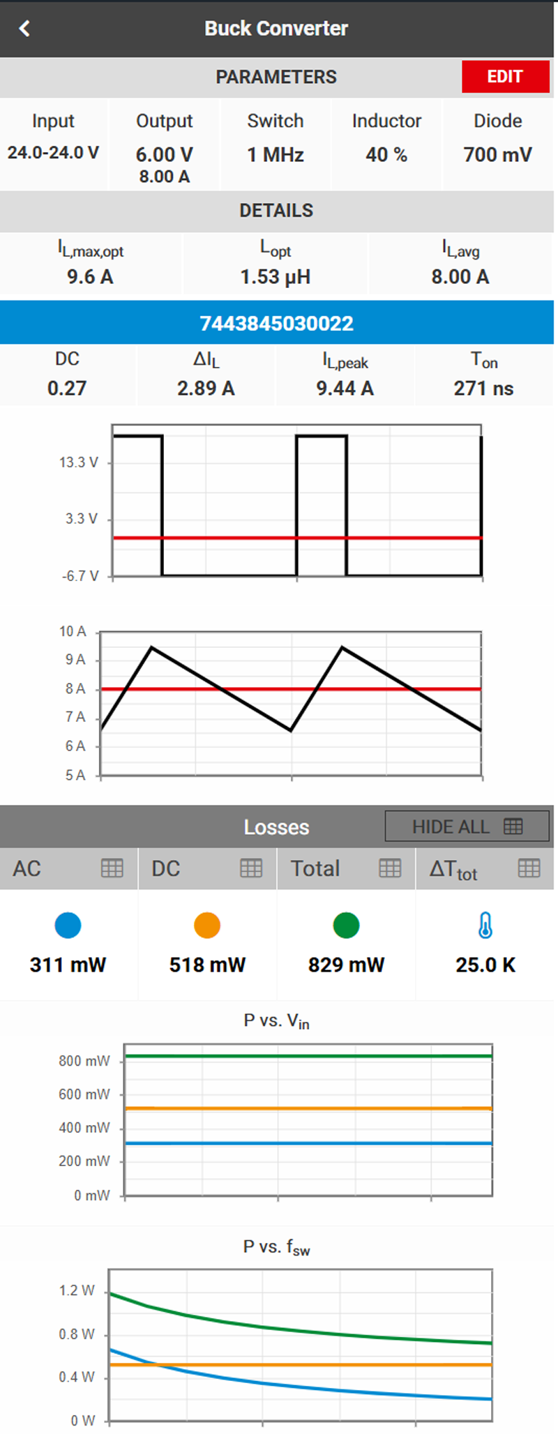
The online tool REDEXPERT developed by Würth Elektronik assists engineers to select a suitable inductor for the respective application, enabling components to be compared and selected within shortest time. Figure 2 shows an example of the REDEXPERT interface for a buck converter. Specific application parameters - such as input and output voltage, switching frequency, duty cycle and output current - are entered, while the corresponding inductor losses and temperature rise are calculated and displayed. The two lower graphs illustrate how power loss varies with input voltage and switching frequency, enabling engineers to evaluate the efficiency of a chosen inductor under varying conditions.
Click image to enlarge
Figure 2: AC and DC losses of a 2.2µH inductor (WE-MXGI) in a buck converter with 24V input voltage, 6V output voltage, 8A output current and 1 MHz switching frequency
Innovative Materials
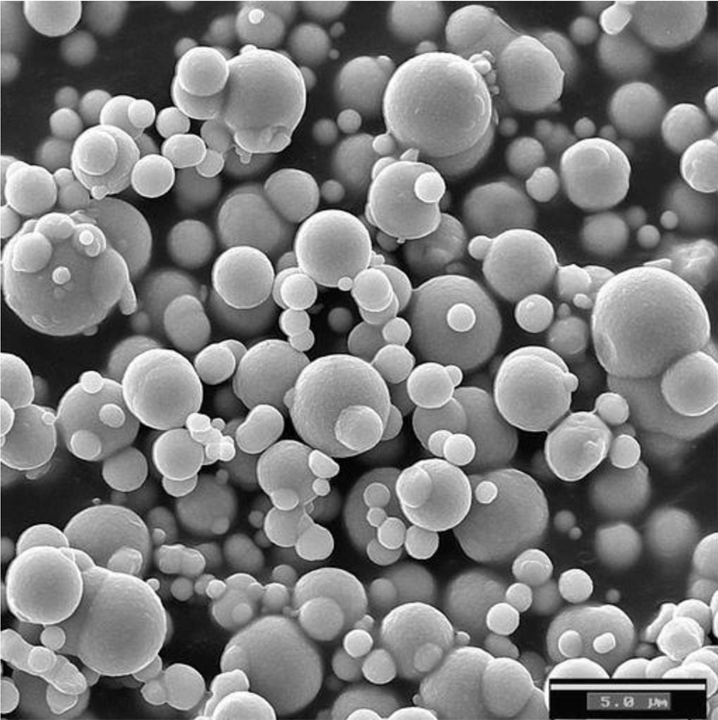
In recent years, molded power inductors based on fine metal powder with a distributed air gap have gained popularity. The material used for the powder consists of pure iron or an iron alloy coated with a thin insulating material. The powder is pressed around the enameled copper winding under high pressure with insulating synthetic resin as a binder agent. The powder particles typically have a crystalline structure in which the iron or other metal ions are arranged in a specific lattice form. The distributed air gap ensures a uniform magnetic flux distribution, enabling high saturation currents and reduced core losses. Figure 3 shows a microscopic view of the powder structure of a molded inductor.
Click image to enlarge
Figure 3: Microscopic analyze of a powder structure of a molded inductor [Zoom: 5 µm]
While crystalline powders provide reliable performance, their magnetic properties can be further enhanced. Recently, amorphous and nanocrystalline materials have gained attention for their ability to enable high-efficiency designs. Amorphous metals exhibit a completely disordered atomic structure, whereas nanocrystalline materials consist of crystalline grains measuring 10-100 nm embedded within an amorphous matrix. This microstructure provides the core with high magnetic permeability, very low coercivity, and minimal magnetic losses in comparison to conventional crystalline magnetic alloys. Because of their excellent soft magnetic properties, nanocrystalline alloys have become a popular magnetic material for a new generation of power molding inductors used in high-frequency electronic applications.
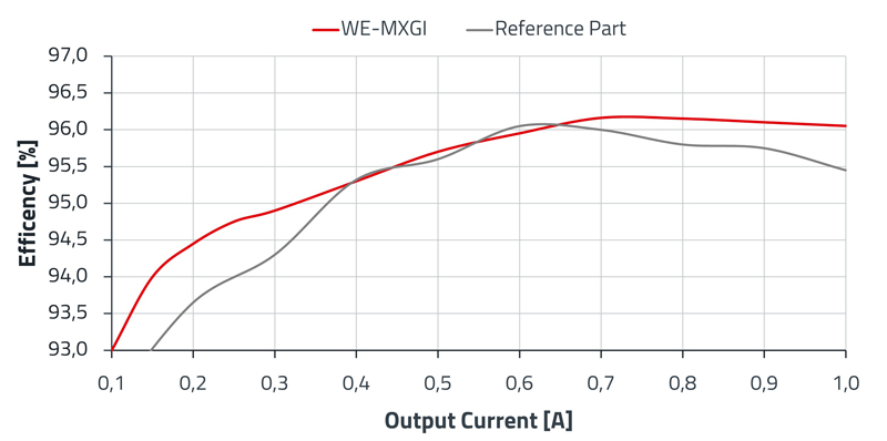
Based on this knowledge, Würth Elektronik offers the newest molded power inductor WE-MXGI. It includes an innovative metal alloy core material that enables maximum power density and excellent current handling capability with minimal losses. Figure 4 shows a comparative efficiency measurement on an evaluation board. Note that the WE-MXGI has top notch efficiency across the output current compared to similar parts on the market.
Click image to enlarge
Figure 4: Efficiency across the output current measurement on an evaluation board of WE-MXGI in comparison to a comparable reference part
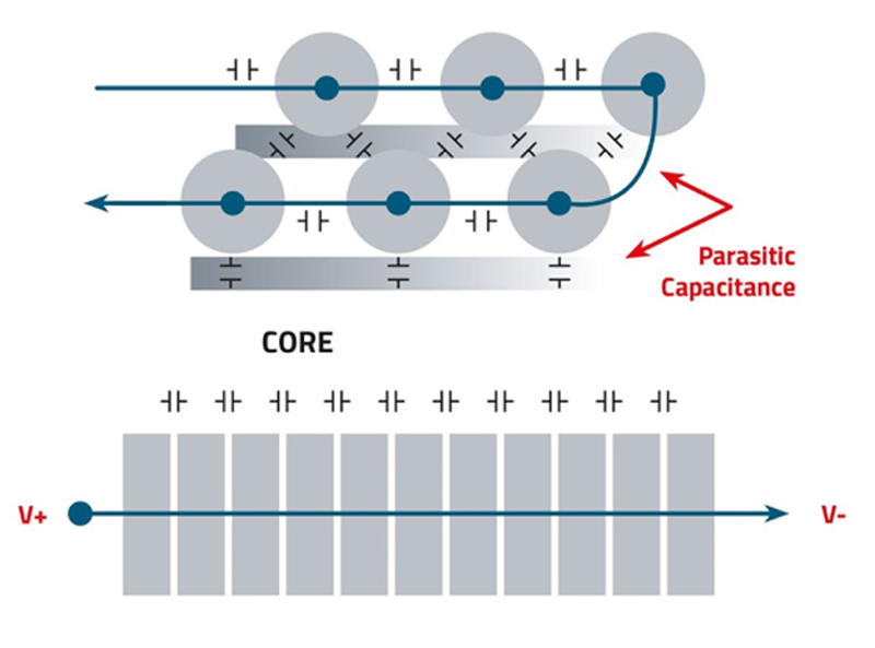
Beyond the choice of the core material the winding design also plays an important role in the total losses of an inductor. In high-frequency applications, flat wire windings are increasingly used. The large conductor cross section reduces current crowding and distributes the electric field uniformly, which minimizes the parasitic capacitance and reduces the EMI effects (Figure 5). By using flat wire low RDC values can be achieved, resulting in reduced DC losses and consequently enhancing converter efficiency.
Click image to enlarge
Figure 5: Flat wire enables uniform distribution of the electrical field, minimizing parasitic capacitance and optimizing EMC effect at the source
With the WE-PMFI and WE-XHMI Performance series, Würth Elektronik has recently introduced inductors that combine an optimized core material mixture with flat wire technology. They are specially designed for low losses to enhance efficiency and minimize self-heating. While the WE-PMFI series focuses on ultra-compact designs, making it ideal for space-constrained electronic devices, the WE-XHMI Performance series covers large footprints to meet the demands of high-current applications.
Future Technologies
Würth Elektronik is actively investing in ongoing research and prototyping, exploring innovative magnetic materials and advanced manufacturing technologies. Development is a continuous process, driven by the rapidly changing demands of dynamic markets. As switching frequencies rise and power densities increase, magnetic components must deliver higher efficiency and better thermal performance in smaller packaging size.
One technology shaping power inductors is based on the principle of combining magnetic powder with a binder system made of polymers. This advanced process enables the production of mechanically robust and reliable power inductors, featuring a high degree of miniaturization and functional integration. Due to its high level of design flexibility, this approach is well suited for applications with strict size and weight constraints, such as compact DC/DC converter designs, where high electrical performance and efficient thermal management is required.
Another approach involves an advanced manufacturing process to produce thermally stable, low-profile inductors. This enables components to be specifically designed for complex multiphase power supply applications, such as high-performance computing platforms, low-profile electronic devices and power modules in data centers and automotive systems. They are engineered to deliver low inductance values for fast transient response, while supporting high saturation currents and minimal DC resistance. This performance is achieved by integrating the magnetic core and conductor into a compact, monolithic structure. The resulting design ensures excellent current handling capability, low electromagnetic interference (EMI) and stable performance across a wide operating temperature range.
Together these advanced manufacturing techniques represent powerful technologies for the next generation of magnetic components. They offer a broad platform for continued innovation and development, paving the way for magnetic solutions that meet the growing demand for compact, thermally efficient, and high-performance power conversion systems.
References
[1] Ermittlung der idealen Speicherinduktivität für energieeffiziente Anwendungen. Application Note ANP031 von Würth Elektronik: www.we-online.com/ANP031
[2] Ritzmann, T.; Stelzer, G.: Speicherinduktivitäten für energieeffiziente Anwendungen. www.elektroniknet.de/e-mechanik-passive/passive/speicherinduktivitaeten-fuer-energieeffiziente-anwendungen.224808.html
[3] BASF Digital Solutions GmbH: Carbonyl Iron Powder [internal] (2022).
[4] Hsiang, H.-I.; Wu, L.-C.; Chen, C.-C.; Lee,W.-H.: Power Molding Inductors Prepared Using Amorphous FeSiCrB Alloy Powder, Carbonyl Iron Powder, and Silicone Resin. Materials 2022, 15, 3681. https://doi.org/10.3390/ma15103681