Low power design – how low is enough?
Designers continue to demand more power in their products to support increased functionality
The portable power application space is both broad and diverse. Products range from wireless sensor nodes (WSNs) that consume average power measured in microwatts to cart-based medical or data acquisition systems with multi-hundred Watt-hour battery packs. However, despite this variety, a few trends emerge – designers continue to demand more power in their products to support increased functionality and look to charge the battery from any available power source.
Consider modern handheld devices – both consumer-oriented devices and industrial devices may include a cellular phone modem, a Wi-Fi module, a Bluetooth module, a large, back-lit display … the list continues. The power architecture of many handheld devices mirrors that of a cell phone. Typically, a 3.7V Li-Ion battery is used as the primary power source due to its high gravimetric (Wh/kg) and volumetric (Wh/m3) energy density. In the past, many high powered devices used a 7.4V Li-ion battery to reduce current requirements, but the availability of inexpensive 5V power management ICs has pushed more and more handhelds to the lower voltage architecture.
The tablet computer illustrates this point well – a typical tablet computer incorporates significant functionality along with a very large (for a portable device) screen. When powered from a 3.7V battery, the capacity must be measured in thousands of milliamp-hours, for example 2200mAh. In order to charge such a battery in hours, thousands of milliamps of charge current are required.
However, this high charge current does not prevent consumers from also wanting to charge their high-powered devices from a USB port if a high current wall adapter is not available. To satisfy these requirements, a battery charger must be able to charge at a high current (>2A) when a wall adapter is available, but still efficiently make use of the 2.5W to 4.5W available from USB.
Furthermore, the product needs to protect sensitive downstream low voltage components from potentially damage-causing overvoltage events and seamlessly direct high currents to the load from a USB input, a wall adapter or the battery while minimizing power loss. This represents an excellent opportunity for battery IC manufactures to develop an IC to safely manage the battery-charging algorithm and monitor critical system parameters.
At the other end of the power spectrum are the nanopower conversion requirements of energy harvesting systems such as those commonly found in WSNs that necessitate the use of power conversion ICs, which deal in very low levels of power and current. These can be 10s of microwatts and nanoamps of current, respectively.
An energy-harvesting WSN
There is plenty of ambient energy in the world around us and the conventional approach for energy harvesting has been through solar panels and wind generators. However, new harvesting tools allow us to produce electrical energy from a wide variety of ambient sources. Furthermore, it is not the energy conversion efficiency of the circuits that is important, but more the amount of “average harvested” energy that is available to power it.
For instance, thermoelectric generators convert heat to electricity, Piezo elements convert mechanical vibration, photovoltaics convert sunlight (or any photon source) and galvanics converter energy from moisture. This makes it possible to power remote sensors, or to charge a storage device such as a capacitor or thin film battery, so that a microprocessor or transmitter can be powered from a remote location without a local power source.
In general terms, the necessary IC performance characteristics needed for inclusion and use in the alternative energy market include the following:
• Low standby quiescent currents – typically less than 6µA and as low as 450nA
• Low start-up voltages – as low as 20mV
• High input voltage capability – up to 34V continuous and 40V transients
• Ability to handle AC inputs
• Multiple output capability and autonomous system power management
• Auto-polarity operation
• Maximum Power Point Control (MPPC) for solar inputs
• The ability to harvest energy from as little as 1°C temperature delta
• Compact solution footprints with minimal external components
WSNs are basically a self-contained system consisting of some kind of transducer to convert the ambient energy source into an electrical signal, usually followed by a DC/DC converter and manager to supply the downstream electronics with the right voltage level and current. The downstream electronics consist of a micro-controller, a sensor and a transceiver.
When trying to implement WSNs, a good question to consider is: How much power do I need to operate it? Conceptually this would seem fairly straight forward; however, in reality it is a little more difficult due to a number of factors. For instance, how frequently does a reading need to be taken? Or, more importantly, how large will the data packet be and how far does it need to be transmitted? This is due to the transceiver consuming approximately 50% of the energy used by the system for a single sensor reading. Several factors affect the power consumption characteristics of an energy harvesting system of WSN.
Of course, the energy provided by the energy-harvesting source depends on how long the source is in operation. Therefore, the primary metric for comparison of scavenged sources is power density, not energy density. Energy harvesting is generally subject to low, variable and unpredictable levels of available power so a hybrid structure that interfaces to the harvester and a secondary power reservoir is often used. The harvester, because of its unlimited energy supply and deficiency in power, is the energy source of the system. The secondary power reservoir, either a battery or a capacitor, yields higher output power but stores less energy, supplying power when required but otherwise regularly receiving charge from the harvester.
Thus, in situations when there is no ambient energy from which to harvest power, the secondary power reservoir must be used to power the WSN. Of course, from a system designer’s perspective, this adds a further degree of complexity since they must now take into consideration how much energy must be stored in the secondary reservoir to compensate for the lack of an ambient energy source. Just how much they will require will depend on several factors.
These will include:
(1) The length of time the ambient energy source is absent
(2) The duty cycle of the WSN (that is the frequency with which a data reading and transmission has to be made)
(3) The size and type of a secondary reservoir (capacitor, supercapacitor or battery)
(4) Is enough ambient energy available to act as both the primary energy source and have sufficient energy left over to charge up a secondary reservoir when it is not available for some specified period?
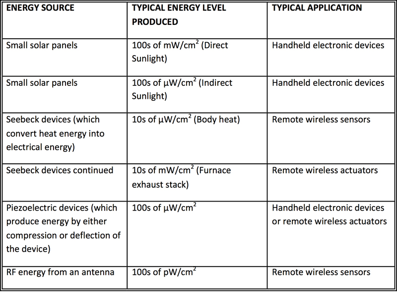
Ambient energy sources include light, heat differentials, vibrating beams, transmitted RF signals, or just about any other source that can produce an electrical charge through a transducer. Table 1 illustrates the amount of energy that can be produced from different energy sources.
Click image to enlarge
Table 1. Energy sources & the amount of energy they can produce
A Nanopower IC Solution
It is clear that WSNs have very low levels of energy available. This, in turn, means that the components used in the system must be able to deal with these low power levels. While this has already been attained with the transceivers and microcontrollers, on the power conversion side of the equation, there has been a void. However, Linear Technology introduced its LTC3388-1/-3 to specifically address this requirement.
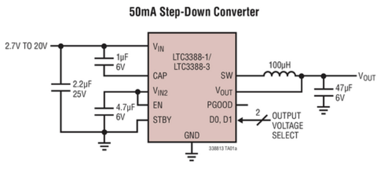
The LTC3388-1/-3 is a 20V input capable synchronous buck converter than can deliver up to 50mA of continuous output current from a 3mm x 3mm (or MSOP10-E) package (see Figure 1). It operates from an input voltage range of 2.7V to 20V, making it ideal for a wide range of energy harvesting and battery-powered applications including “keep-alive” and industrial control power.
Click image to enlarge
Figure 1. LTC3388-1/-3 typlical application schematic
The LTC3388-1/-3 utilizes hysteretic synchronous rectification to optimize efficiency over a wide range of load currents. It can offer over 90% efficiency for loads ranging from 15 μTFA to 50mA and only requires 400nA of quiescent current, enabling it to provide extended battery life. The combination of its 3mm x 3mm DFN package (or MSOP-10) and only five external components offers a very simple and compact solution footprint for a wide array of low power applications.
The LT3388-1/-3 incorporates an accurate undervoltage lock-out (ULVO) feature to disable the converter when the input voltage drops below 2.3V, reducing quiescent current to only 400nA. Once in regulation (at no load), the LTC3388-1/-3 enters a sleep mode to minimize quiescent current to only 720nA. The buck converter then turns on and off as needed to maintain output regulation. An additional standby mode disables switching while the output is in regulation for short duration loads, such as wireless modems, which require low ripple. This high efficiency, low quiescent current design is ideal for applications, such as energy harvesting, which require long charging cycles accompanied by short burst loads for powering sensors and wireless modems.