As power levels have climbed, magnetics manufacturers have striven to produce better-performing components
The latest generation of off-the-shelf inductors for dc-dc converters features flat windings with a helical structure. While this reduces AC losses in many cases, the AC resistance is still considerably higher than the DC resistance and must be considered carefully when selecting your inductor.
Off-The-Shelf Power Inductor Evolution
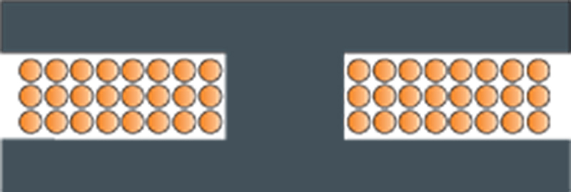
The first generation of off-the shelf inductors from magnetics manufacturers were cheap components with multiple layers of windings on a drum core, as shown in Figure 1. These inductors are fine if you have nothing but dc current flowing through them, but they exhibit extreme losses when an AC component of current is added.
Click image to enalrge
Figure 1: Drum-Core Inductors have Excessive Losses when AC Currents Are Flowing
The high turns count meant many layers of windings are needed, and this leads to very high proximity losses. Furthermore, the windings are placed between the top and bottom pole pieces of the core and fringing losses are large. If you are planning on using inductors like these, be prepared to thermally test them properly, and derate them as needed – frequently more than 50% from the manufacturer’s data sheets.
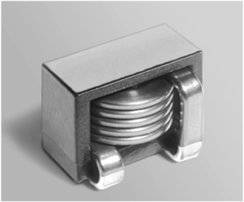
As power levels have climbed, magnetics manufacturers have striven to produce better-performing components while maintaining reasonable prices. An example of the latest generation of parts is shown in Figure 2. This is a foil-wound inductor from Coilcraft, and most manufacturers are now producing similar structures.
Click image to enlarge
Figure 2: Example of Flat-Wound Power Inductor from Coilcraft
Notice that the foil is wound in a helix in a flat turn structure in a special manufacturing process. By winding the inductors this way, a low profile is maintained, and only one layer of turns in used. This should be beneficial for ac loss reduction in the winding. Also, a properly gapped core is used to avoid the excessive fringing losses of early drum-core inductor designs.
Figure 3 shows the structure of the inductor viewed from the side.
Click image to enlarge
Figure 3: Side Drawing of the Windings and Core
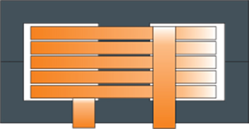
The cross-section of the inductor design is shown in Figure 4, together with some example winding dimensions. The top view of a single inductor turn is also shown. Notice that the equation for the resistance of the winding turn is a more complex expression than might be expected, and it involves the ratio of the inside and outside winding radii.
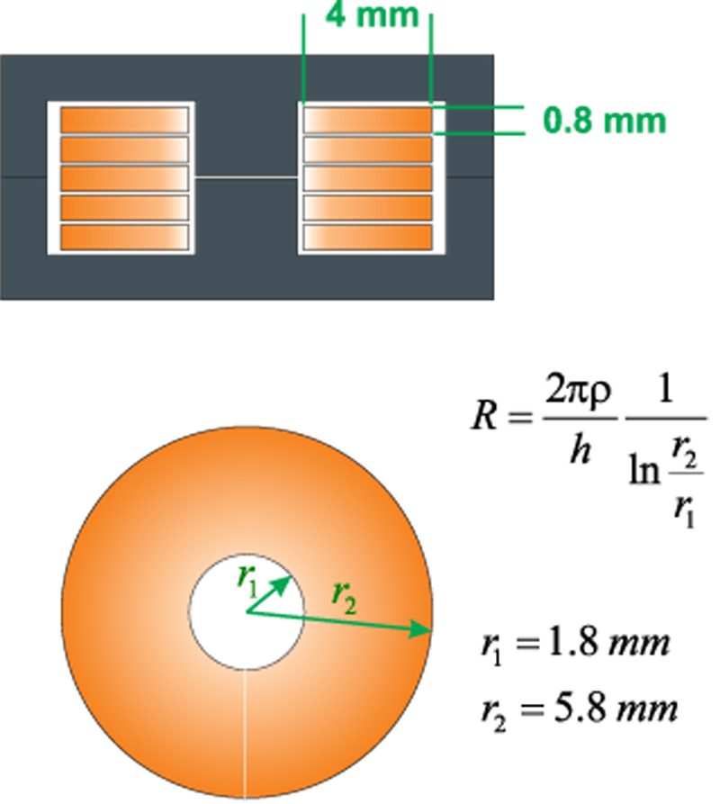
Click image to enlarge
Figure 4: Cross-Section of the Structure and Top View of a Single Turn with Resistance Equation
For five turns of the 0.8 mm foil as shown, the resistance is found from the equation of Figure 4 to be approximately 0.58 mOhm.
AC Resistance of Flat Helical Winding Structure
The flat wound inductor has relatively thin turns, and a single winding layer. This can lead to the erroneous conclusion that it will not suffer from any significant proximity effects at higher frequencies. However, this is not true. While the ac losses may be lower than other structures in many cases, they are still relatively high if a large amount of ac current is flowing.
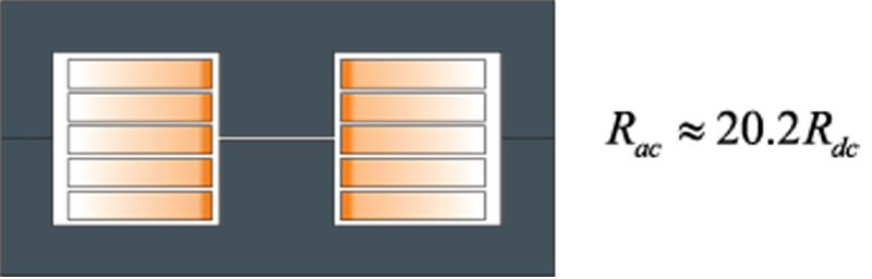
The thin foil does not help the proximity loss since the turns are rotated 90 degrees to the core. At high frequencies, the current will flow only on the inside surface of the conductors, as illustrated in Figure 5. The 4 mm distance across the windings is approximately equal to 38 skin depths at 400 kHz, and only a small portion of the winding will carry any current. It is important that this proximity effect distribution of current be considered when analyzing this type of inductor.
Click image to enlarge
Figure 5: At High Frequencies, the Current Flows on the Inside of the Windings. Even if the Foil is Thin Relative to Skin Depth, AC Resistance is Much Higher than DC Resistance at 400 kHz.
At 400 kHz, the winding resistance is approximately 11.6 mOhm, 20 times higher than it is at DC. While this is high, it may still be a usable inductor since much of the current in a buck converter application will be DC.
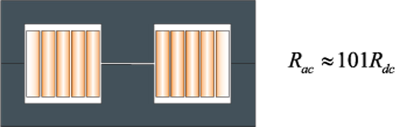
If the same inductor were made of conventional-wound foil, losses will be much higher, as illustrated in Figure 6. In this example, the same profile foil winding is used, but layers are formed on top of each other. This forces both ac and dc current to flow in all windings of the structure. The result is more severe proximity loss, and this is discussed in some detail in [1] and [2]. For the almost identical cross-section winding structure, rotated through 90 degrees, the AC resistance climbs to over 100 times the DC resistance. It is raised from 11.6 mOhm for the helical winding case, to over 62 mOhm. This is quite a surprising result, but it is the reason for the development of the flat-wound inductors.
Click image to enlarge
Figure 6: With 5 Turns, Conventional-Wound Foil Inductor Has Higher AC Resistance at 400 kHz
Looking forward
Flat foil-wound inductors are very popular for higher power applications, providing a reasonable balance of performance and cost for switching converter applications. They are best used with a strong dc current component, and can handle modest amounts of ac ripple. For pure AC applications, such as resonant inductors, they still suffer from high AC losses.
Much better ac inductors can be constructed if the height limitations are relaxed, and higher thickness foils can be used.
Notice that the ac loss situation is complicated further by the fringing losses that may occur if a gapped core is used. It is important to keep the conductors well away from the gap area.
References
[1] Inductor proximity loss article, www.ridleyengineering.com/images/phocadownload/13%20proximity%20loss.pdf
[2] Ridley Engineering hands-on workshop course notes, www.ridleyengineering.com/workshops.html
[3] Proximity Loss Calculator in POWER 4-5-6, www.ridleyengineering.com/software.html
[4] AP300 Application Notes and Videos, www.ridleyengineering.com/analyzer.html
[5] Measuring high-performance loops, https://www.youtube.com/watch?v=CbjtGZtaUaQ
[6] Join our LinkedIn group titled “Power Supply Design Center”. Noncommercial site with over 5300 helpful members with lots of theoretical and practical experience. www.linkedin.com/groups?&gid=4860717
[7] See our videos on power supply design at www.youtube.com/channel/UC4fShOOg9sg_SIaLAeVq19Q